CURRENT ELECTRICITY#
We will make electricity so cheap that only the rich will burn candles - Thomas A. Edison
LEARNING OBJECTIVES#
In this unit, the student is exposed to#
Flow of charges in a metallic conductor. Ohm’s law, electrical resistance, V- I characteristics Carbon resistors and combination of resistors Kirchhoff’s laws - Wheatstone’s bridge and its applications Electric power and Electric energy Heating effect - Joule’s law - applications Thermoelectric effects - Seebeck effect - Peltier effect - Thomson effect
INTRODUCTION#
In unit 1, we studied the properties of charges when they are at rest. In reality, the charges are always moving within the materials. For example, the electrons in a copper wire are never at rest and are continuously in random motion. Therefore it is important to analyse the behaviour of charges when they are in motion. The motion of charges constitutes ’electric current’. Current electricity is the study of flow of electric charges. It owes its origin to Alessandro Volta (1745- 1827), who invented the electric battery which produced the first steady flow of electric current. Modern world depends heavily on the use of electricity. It is used to operate machines, communication systems, electronic devices, home appliances etc., In this unit, we will study about the electric current, resistance and related phenomenon in materials.
2.1 ELECTRIC CURRENT
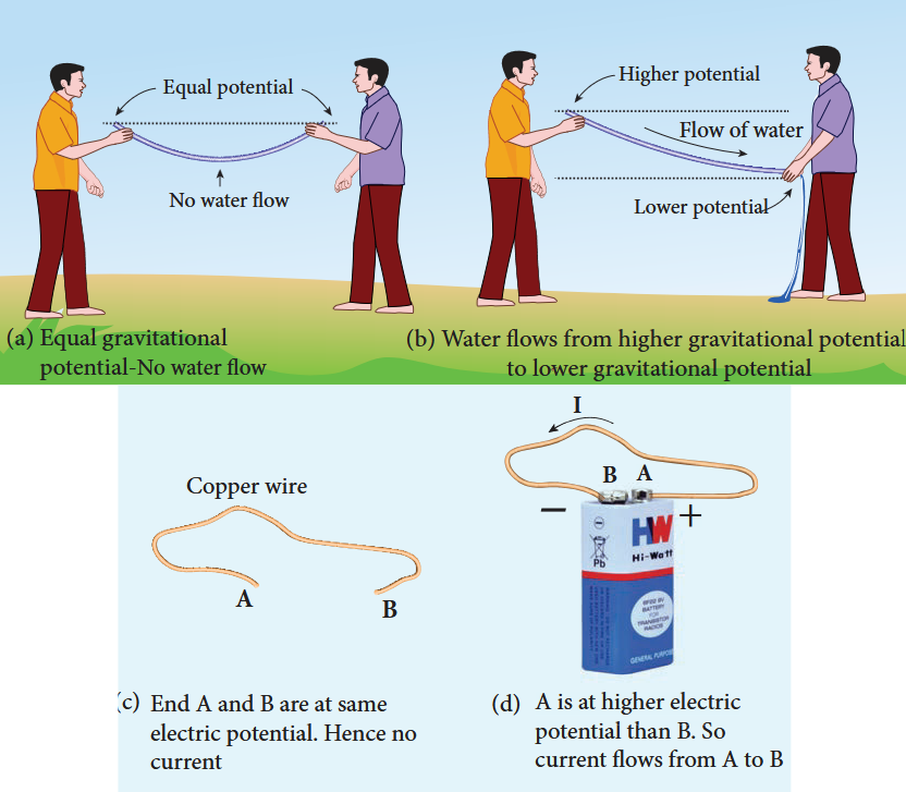
Matter is made up of atoms. Each atom consists of a positively charged nucleus with negatively charged electrons moving around the nucleus. Atoms in metals have one or more electrons which are loosely bound to the nucleus. These electrons are called free electrons and can be easily detached from the atoms. The substances which have an abundance of these free electrons are called conductors. These free electrons move randomly throughout the conductor at a given temperature. In general due to this random motion, there is no net transfer of charges from one end of the conductor to other end and hence no current in the conductor. When a potential difference is applied by the battery across the ends of the conductor, the free electrons drift towards the positive terminal of the battery, producing a net electric current. This is easily understandable from the analogy given in the Figure 2.1.
conductor to other end and hence no current in the conductor. When a potential difference is applied by the battery across the ends of the conductor, the free electrons drift towards the positive terminal of the battery, producing a net electric current. This is easily understandable from the analogy given in the Figure 2.1.
In the XI Volume 2, unit 6, we studied, that the mass move from higher gravitational potential to lower gravitational potential. Likewise, positive charge flows from region of higher electric potential to region of lower electric potential and negative charge flows from region of lower electric potential to region of higher electric potential. So battery or electric cell simply creates potential difference across the conductor.
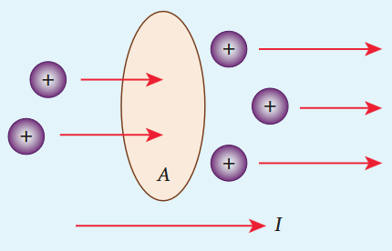
The electric current in a conductor is defined as the rate of flow of charges through a given cross- sectional area A. It is shown in the Figure 2.2.
If a net charge Q passes through any cross section of a conductor in time t, then the current is defined as $I = Q$. But charge flow is not always constant. Hence current can more generally be defined as
$$I_{\mathrm{avg}} = \frac{\Delta Q}{\Delta t} \quad (2.1)$$Where $\Delta Q$ is the amount of charge that passes through the conductor at any cross section during the time interval $\Delta t$ . If the rate at which charge flows changes with time, the current also changes. The instantaneous current I is defined as the limit of the average current, as $\Delta t \rightarrow 0$
$$I = \lim_{\Delta t \to 0} \frac{\Delta Q}{\Delta t} = \frac{dQ}{dt} \quad (2.2)$$The SI unit of current is the ampere (A)
$$1A = \frac{1C}{1s}$$That is, 1A of current is equivalent to 1 coulomb of charge passing through a perpendicular cross section in a conductor in one second. The electric current is a scalar quantity.
EXAMPLE 2.1#
Compute the current in the wire if a charge of 120 C is flowing through a copper wire in 1 minute.
Solution#
The current (rate of flow of charge) in the wire is
$$I = \frac{Q}{t} = \frac{120}{60} = 2A$$2.1.1 Conventional Current#
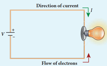
In an electric circuit, arrow heads are used to indicate the direction of flow of current. By convention, this flow in the circuit should be from the positive terminal of the battery to the negative terminal. This current is called the conventional current or simply current and is in the direction in which a positive test charge would move. In typical circuits the charges that flow are actually electrons, from the negative terminal of the battery to the positive terminal. As a result, the flow of electrons and the direction of conventional current point in opposite direction as shown in Figure 2.3. Mathematically, a transfer of positive charge is the
same as a transfer of negative charge in the opposite direction.
Electric current is not only produced by batteries. In nature, lightning bolt produces enormous electric current in a short time. During lightning, very high potential difference is created between the clouds and ground and hence charges flow between the clouds and ground.
2.1.2 Drift velocity#
In a conductor the charge carriers are free electrons. These electrons move freely through the conductor and collide repeatedly with the positive ions. If there is no electric field, the electrons move in random directions, and hence their velocities are also randomly oriented. On an average, the number of electrons travelling in any direction will be equal to the number of electrons travelling in the opposite direction. As a result, there is no net flow of electrons in any direction and hence there will not be any current.
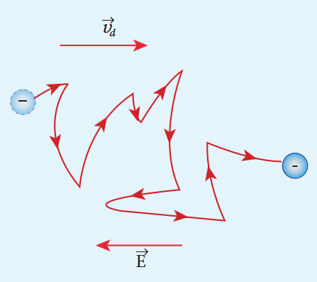
Suppose a potential difference is set across the conductor by connecting a battery, an electric field $\vec{E}$ is created in the conductor. This electric field exerts a force on the electrons, producing a current. The
electric field accelerates the electrons, while ions scatter the electrons and change their direction of motion. Thus, we see zigzag motion of electrons. In addition to the zigzag motion due to the collisions, the electrons move slowly along the conductor in a direction opposite to that of $\vec{E}$ as shown in the Figure 2.4.
Ions#
Any material is made up of neutral atoms with equal number of electrons and protons. If the outermost electrons leave the atoms, they become free electrons and are responsible for electric current. The atoms after losing their outer most electrons will have more positive charges and hence are called positive ions. These ions will not move freely within the material like the free electrons. Hence the positive ions will not give rise to current.
This velocity is called drift velocity $\vec{v}_{d}$ . The drift velocity is the average velocity acquired by the electrons inside the conductor when
is subjected to an electric field. The average time between two successive collisions is called the mean free time denoted by $\tau$ . The acceleration $\bar{a}$ experienced by the electron in an electric field $\bar{E}$ is given by
$$\bar{a} = \frac{-e\bar{E}}{m}\qquad (\mathrm{since}\bar{F} = -e\bar{E}) \quad (2.3)$$The drift velocity $\bar{\nu}_{d}$ is given by
$$\begin{array}{l}\bar{\nu}_{d} = \bar{a}\tau \\ \bar{\nu}_{d} = -\frac{e\tau}{m}\bar{E} \end{array} \quad (2.4)$$Here $\mu = \frac{e\tau}{m}$ is the mobility of the electron and it is defined as the magnitude of the drift velocity per unit electric field.
$$\mu = \frac{|\bar{\nu}_{d}|}{|\bar{E}|} \quad (2.6)$$The SI unit of mobility is $\mathrm{m}^2\mathrm{V}^{- 1}\mathrm{s}^{- 1}$
The typical drift velocity of electrons in the wire is $10^{- 4}\mathrm{ms}^{- 1}$ . If an electron drifts with this speed, then the electrons leaving the battery will take hours to reach the light bulb. Then how electric bulbs glow as soon as we switch on the battery? When battery is switched on, the electrons begin to move away from the negative terminal of the battery and this electron exerts force on the nearby electrons. This process creates a propagating influence (electric field) that travels through the wire at the speed of light. In other words, the energy is transported from the battery to bulb at the speed of light through propagating influence (electric field). Due to this reason, the bulb glows as soon as the battery is switched on.
the light bulb. Then how electric bulbs glow as soon as we switch on the battery? When battery is switched on, the electrons begin to move away from the negative terminal of the battery and this electron exerts force on the nearby electrons. This process creates a propagating influence (electric field) that travels through the wire at the speed of light. In other words, the energy is transported from the battery to bulb at the speed of light through propagating influence (electric field). Due to this reason, the bulb glows as soon as the battery is switched on.
EXAMPLE 2.2#
If an electric field of magnitude $570\mathrm{N}\mathrm{C}^{- 1}$ is applied in the copper wire, find the acceleration experienced by the electron.
Solution:#
$$E = 570\mathrm{N}\mathrm{C}^{-1},e = 1.6\times 10^{-19}\mathrm{C},$$$$m = 9.11\times 10^{-31}\mathrm{kg}\mathrm{and}a = ?$$$$F = ma = eE$$$$a = \frac{eE}{m} = \frac{570\times 1.6\times 10^{-19}}{9.11\times 10^{-31}}$$$$\qquad = \frac{912\times 10^{-19}\times 10^{31}}{9.11}$$$$\qquad = 1.001\times 10^{14}\mathrm{m}\mathrm{s}^{-2}$$Misconception#
(i) There is a common misconception that the battery is the source of electrons. It is not true. When a battery is connected across the given wire, the electrons in the closed circuit resulting the current. Battery sets the potential difference (electrical energy) due to which these electrons in the conducting wire flow in a particular direction. The resulting electrical energy is used by electric bulb, electric fan etc. Similarly the electricity board is supplying the electrical energy to our home.
(ii) We often use the phrases like ‘charging the battery in my mobile’ and ‘my mobile phone battery has no charge’ etc. These sentences are not correct.
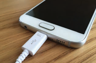
When we say ‘battery has no charge, it means, that the battery has lost ability to provide energy or provide potential difference to the electrons in the circuit. When we say ‘mobile is charging, it implies that the battery is receiving energy from AC power supply and not electrons.
2.1.3 Microscopic model of current#
Consider a conductor with area of cross section A and let an electric field $\vec{E}$ be applied to it from right to left. Suppose there are $n$ electrons per unit volume in the conductor and assume that all the electrons move with the same drift velocity $\vec{v}_{d}$ as shown in Figure 2.5.
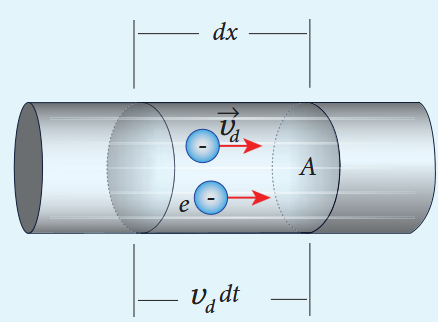
The drift velocity of the electrons $= v_{d}$ If the electrons move through a distance $dx$ within a small interval of $dt$ then
$$v_{d} = \frac{dx}{dt};\quad dx = v_{d}dt \quad (2.7)$$Since A is the area of cross section of the conductor, the electrons available in the volume of length $dx$ is
$=$ volume $\times$ number of electrons per unit volume
$$= A dx\times n \quad (2.8)$$Substituting for $dx$ from equation (2.7) in (2.8)
$$= (A v_{d}dt)n$$Total charge in the volume element $dQ =$ (charge) $\times$ (number of electrons in the volume element)
$$dQ = (e)(Av_{d}dt)n$$$$\mathrm{Hence~the~current~}I = \frac{dQ}{dt}$$$$I = neAv_{d} \quad (2.9)$$Current density (J)#
The current density $(J)$ is defined as the current per unit area of cross section of the conductor.
$$J = \frac{I}{A}$$The S.I unit of current density is $\frac{A}{\mathrm{m}^2}$ (or) $\mathrm{A m}^{- 2}$
$$J = \frac{neAv_{d}}{A} \quad (\text{from equation 2.9})$$$$J = nev_{d} \quad (2.10)$$The above expression is valid only when the direction of the current is perpendicular to the area A. In general, the current density is a vector quantity and it is given by
$$\vec{j} = ne\vec{v}_{d}$$Substituting $\vec{v}_{d}$ from equation (2.4)
$$\begin{array}{l}\vec{j} = -\frac{n\cdot e\cdot\tau}{m}\vec{E}\\ \vec{j} = -\sigma \vec{E} \end{array} \quad (2.11)$$But conventionally, we take the direction of (conventional) current density as the direction of electric field. So the above equation becomes
$$\vec{j} = \sigma \vec{E} \quad (2.12)$$where $\sigma = \frac{ne^2\tau}{m}$ is called conductivity. The equation (2.12) is called microscopic form of ohm’s law.
The inverse of conductivity is called resistivity $(\rho)$ [Refer section 2.2.1].
$$\rho = \frac{1}{\sigma} = \frac{m}{ne^2\tau} \quad (2.13)$$EXAMPLE 2.3#
A copper wire of cross- sectional area $0.5\mathrm{mm}^2$ carries a current of $0.2\mathrm{A}$ . If the free electron density of copper is $8.4\times 10^{28}\mathrm{m}^{- 3}$ then compute the drift velocity of free electrons.
Solution#
The relation between drift velocity of electrons and current in a wire of cross- sectional area A is
$$v_{d} = \frac{I}{neA} = \frac{0.2}{8.4\times 10^{28}\times 1.6\times 10^{-19}\times 0.5\times 10^{-6}}$$$$v_{d} = 0.03\times 10^{-3}\mathrm{m}\mathrm{s}^{-1}$$EXAMPLE 2.4#
Determine the number of electrons flowing per second through a conductor, when a current of 32 A flows through it.
Solution#
$$\mathrm{I} = 32\mathrm{A}, \mathrm{t} = 1\mathrm{s}$$Charge of an electron, $\mathrm{e} = 1.6\times 10^{- 19}\mathrm{C}$
The number of electrons flowing per second, $\mathrm{n} = ?$
$$I = \frac{q}{t} = \frac{ne}{t}$$$$n = \frac{It}{e}$$$$n = \frac{32\times 1}{1.6\times 10^{-19}\mathrm{C}}$$$$n = 20\times 10^{19} = 2\times 10^{20}\mathrm{electrons}$$2.2#
OHM’S LAW#
Why current density is a vector but current is a scalar? In general, the current I is defined as the scalar product of the current density and area vector in which the charges cross.
defined as the scalar product of the current density and area vector in which the charges cross.
$$I = \vec{J}\cdot \vec{A}$$The current I can be positive or negative depending on the choice of the unit vector normal to the surface area A.
The ohm’s law can be derived from the equation $J = \sigma E$ . Consider a segment of wire of length $l$ and cross sectional area $A$ as shown in Figure 2.7.
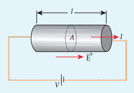
When a potential difference $V$ is applied across the wire, a net electric field is created in the wire which constitutes the current in the wire. For simplicity, we assume that the electric field is uniform in the entire length of the wire, then the potential difference (voltage $V$ ) can be written as
$$V = EI$$As we know, the magnitude of current density
$$J = \sigma E = \sigma \frac{V}{l} \quad (2.14)$$But $J = \frac{I}{A}$ so we write the equation (2.14) as
$$\frac{I}{A} = \sigma \frac{V}{l}.$$By rearranging the above equation, we get
$$V = I\left(\frac{I}{\sigma A}\right) \quad (2.15)$$The quantity $\frac{I}{\sigma A}$ is called resistance of the conductor and it is denoted as $R$ . Note that the resistance is directly proportional to the length of the conductor and inversely proportional to area of cross section.
Therefore, the macroscopic form of Ohm’s law can be stated as “the potential difference across a given conductor is directly proportional to the current passing throught it when the temperature remains constant”.
$$V = IR \quad (2.16)$$From the above equation, the resistance is the ratio of potential difference across the given conductor to the current passing through the conductor.
$$R = \frac{V}{I} \quad (2.17)$$The SI unit of resistance is ohm $(\Omega)$ . From the equation (2.16), we infer that the
graph between current versus voltage is straight line with a slope equal to the inverse of resistance $R$ of the conductor. It is shown in the Figure 2.8 (a).
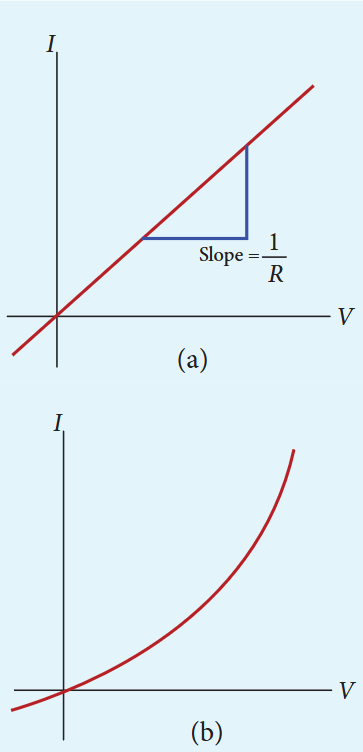
Materials for which the current versus voltage graph is a straight line through the origin, are said to obey Ohm’s law and their behaviour is said to be ohmic as shown in Figure 2.8(a). Materials or devices that do not follow Ohm’s law are said to be non- ohmic. These materials have more complex relationships between voltage and current. A plot of I versus V for a non- ohmic material is non- linear and they do not have a constant resistance (Figure 2.8(b)).
EXAMPLE 2.5#
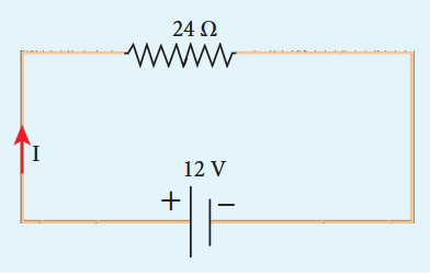
A potential difference across 24 Ω resistor is 12 V. What is the current through the resistor?
Solution#
24 Ω
12 V
+#
\( V = 12 \, \text{V} \) and \( R = 24 \, \Omega \)
Current, \( I = ? \)
From Ohm’s law,
2.1 Resistivity#
In the previous section, we have seen that the resistance $R$ of any conductor is given by
$$R = \frac{I}{\sigma A} \quad (2.18)$$where $\sigma$ is called the conductivity of the material and it depends only on the type of the material used and not on its dimension.
The resistivity of a material is equal to the reciprocal of its conductivity.
$$\rho = \frac{1}{\sigma} \quad (2.19)$$Now we can rewrite equation (2.18) using equation (2.19)
$$R = \rho \frac{I}{A} \quad (2.20)$$The resistance of a material is directly proportional to the length of the conductor and inversely proportional to the area of cross section of the conductor. The
proportionality constant $\rho$ is called the resistivity of the material.
If $l = 1\mathrm{m}$ and $A = 1\mathrm{m}^2$ , then the resistance $R = \rho$ . In other words, the electrical resistivity of a material is defined as the resistance offered to current flow by a conductor of unit length having unit area of cross section. The SI unit of $\rho$ is ohm- metre $(\Omega \mathrm{m})$ . Based on the resistivity, materials are classified as conductors, insulators and semiconductors. The conductors have lowest resistivity, insulators have highest resistivity and semiconductors have resistivity greater than conductors but less than insulators. The typical resistivity values of some conductors, insulators and semiconductors are given in the Table 2.1
| Table 2.1 Resistivity for various materials | |
| Material | Resistivity, ρ (Ω m) at 20℃ |
| Insulators | |
| Pure Water | 2.5 × 10⁻⁵ |
| Glass | 1010 – 1014 |
| Hard Rubber | 1013 – 1016 |
| NaCl | 1014 |
| Fused Quartz | 1016 |
| Semiconductors | |
| Germanium | 0.46 |
| Silicon | 640 |
| Conductors | |
| Silver | 1.6 × 10⁻⁸ |
| Copper | 1.7 × 10⁻⁸ |
| Aluminium | 2.7 × 10⁻⁸ |
| Tungsten | 5.6 × 10⁻⁸ |
| Iron | 10 × 10-8 |
EXAMPLE 2.6#
The resistance of a wire is $20\Omega$ .What will be new resistance, if it is stretched uniformly 8 times its original length?
Solution#
$$R_{1} = 20\Omega ,R_{2} = ?$$Let the original length of the wire $(l_{1})$ be $l$
New length, $l_{2} = 8l_{1}(i,e)l_{2} = 8l$
Original resistance, $R_{1} = \rho \frac{l_{1}}{A_{1}}$
New resistance $R_{2} = \rho \frac{l_{2}}{A_{2}} = \frac{\rho(8l)}{A_{2}}$
Though the wire is stretched, its volume remains unchanged.
Initial volume $=$ Final volume
$$A_{1}l_{1} = A_{2}l_{2},\qquad A_{1}l = A_{2}(8l)$$$$\frac{A_1}{A_2} = \frac{8l}{l} = 8$$By dividing equation for $R_{2}$ by equation for $R_{1}$ , we get
$$\frac{R_{2}}{R_{1}} = \frac{\rho(8l)}{A_{2}}\times \frac{A_{1}}{\rho l}$$$$\frac{R_{2}}{R_{1}} = \frac{A_{1}}{A_{2}}\times 8$$Substituting the value of $\frac{A_{1}}{A_{2}}$ , we get
$$\frac{R_{2}}{R_{1}} = 8\times 8 = 64$$$$R_{2} = 64\times 20 = 1280\Omega$$Hence, stretching the length of the wire has increased its resistance.
EXAMPLE 2.7#
Consider a rectangular block of metal of height A, width B and length C as shown in the figure.
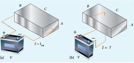
If a potential difference of $V$ is applied between the two faces A and B of the block (figure (a)), the current $I_{AB}$ is observed. Find the current that flows if the same potential difference $V$ is applied between the two faces B and C of the block (figure (b)). Give your answers in terms of $I_{AB}$ .
Solution#
In the first case, the resistance of the block
$$R_{AB} = \rho \frac{\mathrm{length}}{\mathrm{Area}} = \rho \frac{C}{AB}$$The current $I_{AB} = \frac{V}{R_{AB}} = \frac{V}{\rho}\frac{AB}{C}$ (1)
In the second case, the resistance of the block $R_{BC} = \rho \frac{A}{BC}$
The current $I_{BC} = \frac{V}{R_{BC}} = \frac{V}{\rho}\frac{BC}{A}$ (2)
To express $I_{BC}$ interms of $I_{AB}$ , we multiply and divide equation (2) by AC, we get
$$I_{BC} = \frac{V}{\rho}\frac{BC}{A}\frac{AC}{AC} = \left(\frac{V}{\rho}\frac{AB}{C}\right)\frac{C^{2}}{A^{2}} = \frac{C^{2}}{A^{2}}\cdot I_{AB}$$Since $C > A$ , the current $I_{BC} > I_{AB}$
The human body contains a large amount of water which has low resistance of around $200\Omega$ and the dry skin has high resistance of around $500\mathrm{k}\Omega$ . But when the skin is wet, the resistance is reduced to around $1000\Omega$ . This is the reason why repairing the electrical connection with the wet skin is always dangerous.
2.2.2 Resistors in series and parallel#
An electric circuit may contain a number of resistors which can be connected in different ways. For each type of circuit, we can calculate the equivalent resistance produced by a group of individual resistors.
Resistors in series#
When two or more resistors are connected end to end, they are said to be in series. The resistors could be simple resistors or bulbs or heating elements or other devices. Figure 2.9 (a) shows three resistors $R_{1},R_{2}$ and $R_{3}$ connected in series.
The amount of charge passing through resistor $R_{1}$ must also pass through resistors $R_{2}$ and $R_{3}$ since the charges cannot accumulate anywhere in the circuit. Due to
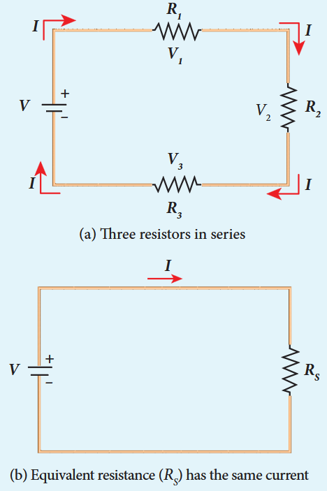
this reason, the current I passing through all the three resistors is the same. According to Ohm’s law, if same current pass through different resistors of different values, then the potential difference across each resistor must be different. If $V_{1},V_{2}$ and $V_{3}$ be the potential differences (voltage) across each of the resistors $R_{1},R_{2}$ and $R_{3}$ respectively, then we can write $V_{1} = IR_{1}$ $V_{2} = IR_{2}$ and $V_{3} = IR_{3}$ . But the supply voltage $V$ must be equal to the sum of voltages(potential differences) across each resistor.
$$V = V_{1} + V_{2} + V_{3} = IR_{1} + IR_{2} + IR_{3} \quad (2.21)$$$$V = I(R_{1} + R_{2} + R_{3})$$$$V = IR_{S}$$where $R_{s}$ is the equivalent resistance.
$$R_{s} = R_{1} + R_{2} + R_{3} \quad (2.23)$$When several resistors are connected in series, the total or equivalent resistance is the sum of the individual resistances as shown in the Figure 2.9 (b).
Note: The value of equivalent resistance in series connection will be greater than each individual resistance.
EXAMPLE 2.8#
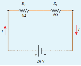
Calculate the equivalent resistance for the circuit which is connected to $24\mathrm{V}$ battery and also find the potential difference across each resistors in the circuit.
Solution#
Since the resistors are connected in series, the effective resistance in the circuit
$$= 4\Omega +6\Omega = 10\Omega$$current I in the circuit $= \frac{V}{R_{eq}} = \frac{24}{10} = 2.4A$
Voltage across $4\Omega$ resistor
$$V_{1} = IR_{1} = 2.4\mathrm{A}\times 4\Omega = 9.6\mathrm{V}$$Voltage across $6\Omega$ resistor
$$V_{2} = IR_{2} = 2.4\mathrm{A}\times 6\Omega = 14.4\mathrm{V}$$Resistors in parallel#
Resistors are in parallel when they are connected across the same potential difference as shown in Figure 2.10 (a).
In this case, the total current I that leaves the battery is split into three separate components. Let $I_{1}, I_{2}$ and $I_{3}$ be the current through the resistors $R_{1}, R_{2}$ and $R_{3}$ respectively. Due to the conservation of charge, total current in the circuit I is equal to sum of the currents through each of the three resistors.
$$I = I_{1} + I_{2} + I_{3} \quad (2.24)$$Since the voltage across each resistor is the same, applying Ohm’s law to each resistor, we have
$$I_{1} = \frac{V}{R_{1}},I_{2} = \frac{V}{R_{2}},I_{3} = \frac{V}{R_{3}} \quad (2.25)$$Substituting these values in equation (2.24), we get
$$I = \frac{V}{R_{1}} +\frac{V}{R_{2}} +\frac{V}{R_{3}} = V\left[\frac{1}{R_{1}} +\frac{1}{R_{2}} +\frac{1}{R_{3}}\right]$$$$I = \frac{V}{R_{p}}$$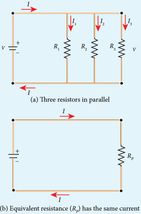
Here $R_{p}$ is the equivalent resistance of the parallel combination of the resistors. Thus, when a number of resistors are connected in parallel, the sum of the reciprocals of resistance of the individual resistors is equal to the reciprocal of the effective resistance of the combination as shown in the Figure 2.10 (b).
Note: The value of equivalent resistance in parallel connection will be lesser than each individual resistance.
House hold appliances are always connected in parallel so that even if one is switched off, the other devices could function properly.
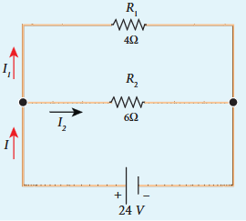
EXAMPLE 2.9#
Calculate the equivalent resistance in the following circuit and also find the values of current $I, I_1$ and $I_2$ in the given circuit.
Solution#
Since the resistances are connected in parallel, the equivalent resistance in the circuit is
$$\frac{1}{R_p} = \frac{1}{R_1} +\frac{1}{R_2} = \frac{1}{4} +\frac{1}{6}$$$$\frac{1}{R_p} = \frac{5}{12}\Omega \mathrm{or}R_p = \frac{12}{5}\Omega$$The resistors are connected in parallel, the potential difference (voltage) across them is the same.
The current $I$ is the sum of the currents in the two branches. Then,
$$I = I_1 + I_2 = 6\mathrm{A} + 4\mathrm{A} = 10\mathrm{A}$$EXAMPLE 2.10#
Two resistors when connected in series and parallel, their equivalent resistances are $15\Omega$ and $\frac{56}{15}\Omega$ respectively. Find the values of the resistances.
Solution#
$$\begin{array}{l}{R_{\mathrm{s}} = R_{1} + R_{2} = 15\Omega}\\ {R_{p} = \frac{R_{1}R_{2}}{R_{1} + R_{2}} = \frac{56}{15}\Omega} \end{array} \quad (1)$$From equation (1) substituting for $R_{1} + R_{2}$ in equation (2)
$$\frac{R_{1}R_{2}}{15} = \frac{56}{15}\Omega$$$$\therefore R_{1}R_{2} = 56$$$$R_{2} = \frac{56}{R_{1}}\Omega \quad (3)$$Substituting for $R_{2}$ in equation (1) from equation (3)
$$R_{1} + \frac{56}{R_{1}} = 15$$$$\mathrm{Then},\frac{R_{1}^{2} + 56}{R_{1}} = 15$$$$R_{1}^{2} + 56 = 15R_{1}$$$$R_{1}^{2} - 15R_{1} + 56 = 0$$The above equation can be solved using factorisation.
$$R_{1} = 8\Omega (\mathrm{or})R_{1} = 7\Omega$$$$\mathrm{If}R_{1} = 8\Omega$$Substituting in equation (1)
$$8 + R_{2} = 15$$$$R_{2} = 15 - 8 = 7\Omega ,$$$$R_{2} = 7\Omega \mathrm{i.e.,}(\mathrm{when}R_{1} = 8\Omega ;R_{2} = 7\Omega)$$$$\mathrm{If}R_{1} = 7\Omega$$Substituting in equation (1)
$$7 + R_{2} = 15$$$$R_{2} = 8\Omega ,\mathrm{i.e.,}(\mathrm{when}R_{1} = 7\Omega ;R_{2} = 8\Omega)$$EXAMPLE 2.11#
Calculate the equivalent resistance between A and B in the given circuit.
Circuit Diagram
Solution#
In all the sections, the resistors are connected in parallel.
Section 1#
\[ \frac{1}{R_A} = \frac{1}{R_1} + \frac{1}{R_2} \]\[ \frac{1}{R_A} = \frac{1}{2} + \frac{1}{2} = \frac{2}{2} = 1 \, \Omega \]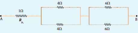
Section II#
\[ \frac{1}{R_A} = \frac{1}{4} + \frac{1}{4} = \frac{2}{4} = \frac{1}{2} \; R_A = 2 \, \Omega \]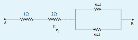
Section III#
\[ \frac{1}{R_A} = \frac{1}{6} + \frac{1}{6} = \frac{2}{6} = \frac{1}{3} \; R_A = 3 \, \Omega \]Equivalent resistance is given by
\[ R = R_A + R_B + R_C \]\[ R = 1 \, \Omega + 2 \, \Omega + 3 \, \Omega = 6 \, \Omega \]The circuit becomes,
Equivalent resistance between A and B is
EXAMPLE 2.12#
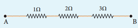
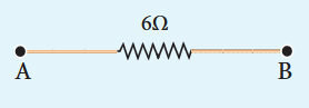
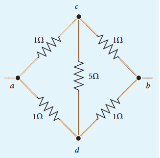
Five resistors are connected in the configuration as shown in the figure. Calculate the equivalent resistance between the points a and b.
Solution#
Case (a)#
To find the equivalent resistance between the points a and b, we assume that a current is entering the junction at a. Since all the resistances in the outside loop are the same (\(1 \, \Omega\)), the current in the branches ac and ad must be equal. Hence the points C and D are at the same potential and no current through \(5 \, \Omega\). It implies that the \(5 \, \Omega\) has no role in determining the equivalent resistance and it can be removed. So the circuit is simplified as shown in the figure.
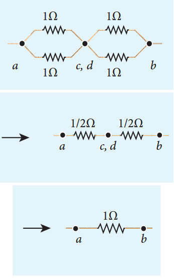
The equivalent resistance of the circuit between a and b is $R_{eq} = 1\Omega$
2.2.3 Colour code for Carbon resistors#
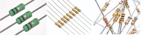
Carbon resistors consists of a ceramic core, on which a thin layer of crystalline carbon is deposited as shown in Figure 2.11. These resistors are inexpensive, stable and compact in size. Colour rings are used to indicate the value of the resistance according to the rules given in the Table 2.2.
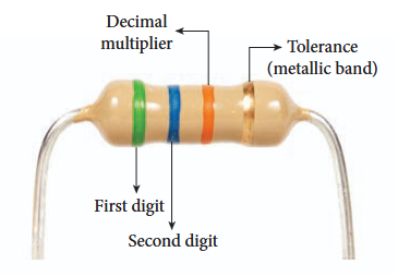
Three coloured rings are used to indicate the values of a resistor: the first two rings are significant figures of resistances, the third ring indicates the decimal multiplier after them. The fourth colour, silver or gold, shows the tolerance of the resistor at $10%$ or $5%$ as shown in the Figure 2.12. If there is no fourth ring, the tolerance is $20%$ .
Table 2.2 Colour Coding for Resistors
| Colour | Number | Multiplier | Tolerance |
|---|---|---|---|
| Black | 0 | 1 | |
| Brown | 1 | 10 | 1 |
| Red | 2 | 10^2 | |
| Orange | 3 | 10^3 | |
| Yellow | 4 | 10^4 | |
| Green | 5 | 10^5 | |
| Blue | 6 | 10^6 | |
| Violet | 7 | 10^7 | |
| Gray | 8 | 10^8 | |
| White | 9 | 10^9 | |
| Gold | 10^{-1} | 5% | |
| Silver | 10^{-2} | 10% | |
| Colourless | 20% |
shows the tolerance of the resistor at $10%$ or $5%$ as shown in the Figure 2.12. If there is no fourth ring, the tolerance is $20%$ .
For the resistor shown in Figure 2.12, the first digit $= 5$ (green), the second digit $= 6$ (blue), decimal multiplier $= 10^{3}$ (orange) and tolerance $= 5%$ gold). The value of resistance $= 56\times 10^{3}\Omega$ or $56\mathrm{k}\Omega$ with the tolerance value $5%$ .
2.2.4 Temperature dependence of resistivity#
The resistivity of a material is dependent on temperature. It is experimentally found that for a wide range of temperatures, the resistivity of a conductor increases with increase in temperature according to the expression,
$$\rho_{T} = \rho_{0}\big[1 + \alpha (T - T_{0})\big] \quad (2.27)$$where $\rho_{T}$ is the resistivity of a conductor at $T^{\circ}C$ $\rho_{0}$ is the resistivity of the conductor at some reference temperature $T_{0}$ usually at $20^{\circ}C$ and $\alpha$ is the temperature coefficient of resistivity. It is defined as the ratio of increase in resistivity per degree rise in temperature to its resistivity at $T_{0}$
From the equation (2.27), we can write
$$\rho_{T} - \rho_{0} = \alpha \rho_{0}(T - T_{0})$$$$\therefore \alpha = \frac{\rho_{T} - \rho_{0}}{\rho_{0}(T - T_{0})} = \frac{\Delta\rho}{\rho_{0}\Delta T}$$where $\Delta \rho = \rho_{T} - \rho_{0}$ is change in resistivity for a change in temperature $\Delta T = T - T_{0}$ Its unit is per $^\circ \mathrm{C}$
$\alpha$ of conductors#
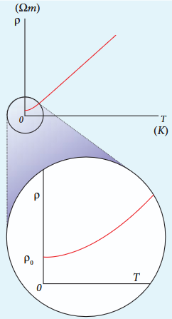
For conductors $\alpha$ is positive. If the temperature of a conductor increases, the average kinetic energy of electrons in the conductor increases. This results in more frequent collisions and hence the resistivity increases. The graph of the equation (2.27) is shown in Figure 2.13.
Even though, the resistivity of conductors like metals varies linearly for wide range of temperatures, there also exists a nonlinear region at very low temperatures. The resistivity approaches some finite value as the temperature approaches absolute zero as shown in Figure 2.13(b).
Using the equation $\rho = R\frac{A}{l}$ in equation (2.27), we get the expression for the resistance of a conductor at temperature $T^{\circ}C$ as
$$R_{T} = R_{0}\left[1 + \alpha (T - T_{0})\right] \quad (2.28)$$The temperature coefficient of resistivity can also be obtained from the equation (2.28),
$$\begin{array}{l}{R_{T} - R_{0} = \alpha R_{0}(T - T_{0})}\\ {\therefore \alpha = \frac{R_{T} - R_{0}}{R_{0}(T - T_{0})} = \frac{1}{R_{0}}\frac{\Delta R}{\Delta T}}\\ {\alpha = \frac{1}{R_{0}}\frac{\Delta R}{\Delta T}} \end{array} \quad (2.29)$$where $\Delta R = R_{T} - R_{0}$ is change in resistance during the change in temperature $\Delta T = T - T_{0}$
$\alpha$ of semiconductors#
For semiconductors, the resistivity decreases with increase in temperature. As the temperature increases, more electrons will be liberated from their atoms (Refer unit 9 for conduction in semi conductors).
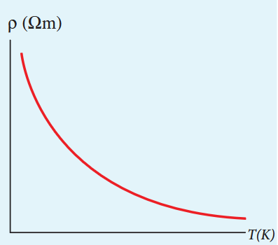
Figure 2.14 Temperature dependence of resistivity for a semiconductor
Hence the current increases and therefore the resistivity decreases as shown in Figure 2.14. A semiconductor with a negative temperature coefficient of resistivity is called a thermistor.
The typical values of temperature coefficients of various materials are given in table 2.3.
| Table 2.3 | |
| Material | Temperature Coefficient of resistivity α [(°C)-1] |
| Silver | 3.8 × 10⁻³ |
| Copper | 3.9 × 10⁻³ |
| Gold | 3.4 × 10⁻³ |
| Aluminum | 3.9 × 10⁻³ |
| Tungsten | 4.5 × 10⁻³ |
| Iron | 5.0 × 10⁻³ |
| Platinum | 3.92 × 10⁻³ |
| Lead | 3.9 × 10⁻³ |
| Nichrome | 0.4 × 10⁻³ |
| Carbon | -0.5 × 10⁻³ |
| Germanium | -48 × 10-3 |
| Silicon | -75 × 10-3 |
We can understand the temperature dependence of resistivity in the following way. In section 2.1.3, we have shown that the electrical conductivity, $\sigma = \frac{ne^2\tau}{m}$ . As the resistivity is inverse of $\sigma$ , it can be written as
$$\rho = \frac{m}{ne^2\tau} \quad (2.30)$$The resistivity of materials is
i) inversely proportional to the number density $(n)$ of the electrons ii) inversely proportional to the average time between the collisions $(\tau)$
In metals, if the temperature increases, the average time between the collision $(\tau)$ decreases and $n$ is independent of temperature. In semiconductors when temperature increases, $n$ increases and $\tau$ decreases, but increase in $n$ is dominant than decreasing $\tau$ so that overall resistivity decreases.
The resistance of certain materials become zero below certain temperature $T_{c}$ . This temperature is known as critical temperature or transition temperature. The materials which exhibit this property are known as superconductors. This phenomenon was first observed by Kammerlingh Onnes in 1911. He found that mercury exhibits superconductor behaviour at 4.2 K. Since $R = 0$ , current once induced in a superconductor persists without any potential difference.
EXAMPLE 2.13#
If the resistance of coil is $3\Omega$ at $20^{\circ}C$ and $\alpha = 0.004 / 0C$ then determine its resistance at $100^{\circ}C$
2.3
Solution#
$$R_{0} = 3\Omega ,\quad \mathrm{T} = 100^{\circ}\mathrm{C},\quad T_{0} = 20^{\circ}\mathrm{C}$$$$\alpha = 0.004 / ^{\circ}\mathrm{C},\quad R_{T} = ?$$$$R_{T} = R_{0}(1 + \alpha (T - T_{0}))$$$$R_{100} = 3(1 + 0.004\times 80)$$$$R_{100} = 3.96\Omega$$EXAMPLE 2.14#
Resistance of a material at $20^{\circ}\mathrm{C}$ and $40^{\circ}\mathrm{C}$ are $45\Omega$ and $85\Omega$ respectively. Find its temperature coefficient of resistivity.
Solution#
$$\mathrm{T}_0 = 20^{\circ}\mathrm{C},\mathrm{T} = 40^{\circ}\mathrm{C},\mathrm{R}_0 = 45\Omega ,\mathrm{R} = 85\Omega$$$$\alpha = \frac{1}{R_0}\frac{\Delta R}{\Delta T}$$$$\alpha = \frac{1}{45}\left(\frac{85 - 45}{40 - 20}\right) = \frac{1}{45} (2)$$$$\alpha = 0.044\mathrm{per}^{\circ}\mathrm{C}$$ENERGY AND POWER IN ELECTRICAL CIRCUITS#
When a battery is connected between the ends of a conductor, a current is established. The battery is supplying energy to the device which is connected in the circuit. Consider a circuit in which a battery of voltage V is connected to the resistor as shown in Figure 2.15. Assume that a positive charge of dQ moves from point a to b through the battery and moves from point c to d through the resistor and back to point a. When the charge
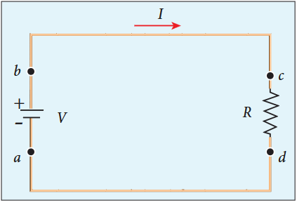
moves from point $a$ to $b$ it gains potential energy $dU = V.dQ$ and the chemical potential energy of the battery decreases by the same amount. When this charge $dQ$ passes through resistor it loses the potential energy $dU = V.dQ$ due to collision with atoms in the resistor and again reaches the point $a$ . This process occurs continuously till the battery is connected in the circuit. The rate at which the charge loses its electrical potential energy in the resistor can be calculated.
The electrical power $\mathrm{P}$ is the rate at which the electrical potential energy is delivered,
$$P = \frac{dU}{dt} = \frac{(V.dQ)}{dt} = V\frac{dQ}{dt} \quad (2.31)$$Since the electric current $I = \frac{dQ}{dt}$ , the equation (2.31) can be rewritten as
When a battery is connected between the ends of a conductor, a current is established. The battery is supplying energy to the device which is connected in the circuit. Consider a circuit in which a battery of voltage $V$ is connected to the resistor as shown in Figure 2.15.
Assume that a positive charge of $dQ$ moves from point $a$ to $b$ through the battery and moves from point $c$ to $d$ through the resistor and back to point $a$ . When the charge
$$P = VI \quad (2.32)$$This expression gives the power delivered by the battery to any electrical system, where $I$ is the current passing through it and $V$ is the potential difference across it. The SI unit of electrical power is watt $(1W = 1\mathrm{J}\mathrm{s}^{- 1})$ . Commercially, the electrical bulbs used in houses come with the power and voltage rating of 5W- 220V, 30W- 220V, 60W- 220V etc. (Figure 2.16).
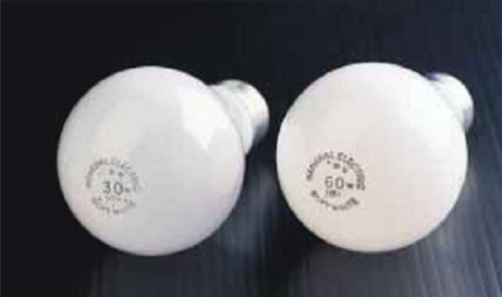
Usually these voltage rating refers AC RMS voltages. For a given bulb, if the voltage drop across the bulb is greater than voltage rating, the bulb will fuse.
Using Ohm’s law, power delivered to the resistance R is expressed in other forms
$$\begin{array}{l}P = IV = I(IR) = PR\\ P = IV = \frac{V}{R} V = \frac{V^2}{R} \end{array} \quad (2.34)$$The total electrical energy used by any device is obtained by multiplying the power and duration of the time when it is ON. If the power is in watts and the time is in seconds, the energy will be in joules. In practice, electrical energy is measured in kilowatt hour (kWh). 1 kWh is known as 1 unit of electrical energy.
(1 kWh $= 1000$ Wh $= (1000$ W) (3600 s) $= 3.6\times 10^{6}$ J)
EXAMPLE 2.15#
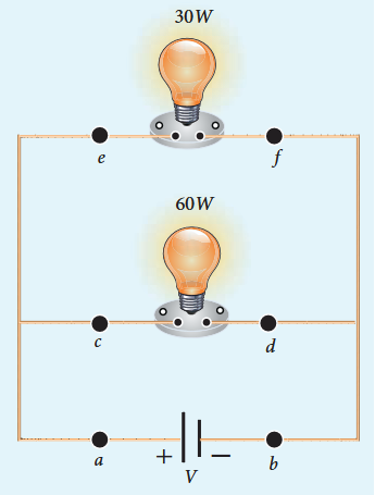
A battery of voltage V is connected to 30 W bulb and 60 W bulb as shown in the figure. (a) Identify brightest bulb (b) which bulb has greater resistance? (c) Suppose the two bulbs are connected in series, which bulb will glow brighter?
Solution#
The power delivered by the battery $P = VI$ . Since the bulbs are connected in parallel, the voltage drop across each bulb is the same. If the voltage is kept fixed, then the power is directly proportional to current $(P \propto I)$ . So 60 W bulb draws twice as much as current as 30 W and it will glow brighter than 30 W bulb.
(b) To calculate the resistance of the bulbs, we use the relation $P = \frac{V^2}{R}$ . In both the bulbs, the voltage drop is the same. So the power is inversely proportional to the resistance or resistance is inversely proportional to the power $\left(R \propto \frac{1}{P}\right)$ . It implies that, the 30W has twice as much as resistance as 60 W bulb.
(c) When the bulbs are connected in series, the current passing through each bulb is the same. It is equivalent to two resistors connected in series. The bulb which has higher resistance has higher voltage drop. So 30W bulb will glow brighter than 60W bulb. So the higher power rating does not always imply more brightness and it depends whether bulbs are connected in series or parallel.
EXAMPLE 2.16#
Two electric bulbs marked $20\mathrm{W} - 220\mathrm{V}$ and $100\mathrm{W} - 220\mathrm{V}$ are connected in series to $440\mathrm{V}$ supply. Which bulb will get fused?
Solution#
To check which bulb will get fused, the voltage drop across each bulb has to be calculated.
The resistance of the bulb,
For 100W- 220V bulb,
$$R_{2} = \frac{(220)^{2}}{100}\Omega = 484\Omega$$Both the bulbs are connected in series. So same current will pass through both the bulbs. The current that passes through the circuit, $I = \frac{V}{R_{tot}}$ .
$$R_{tot} = (R_1 + R_2)$$$$R_{tot} = (484 + 2420)\Omega = 2904\Omega$$$$I = \frac{440V}{2904\Omega}\approx 0.151\mathrm{A}$$The voltage drop across the 20W bulb is
$$V_{1} = IR_{1} = \frac{440}{2904}\times 2420\approx 366.6\mathrm{V}$$The voltage drop across the 100W bulb is
$$V_{2} = IR_{2} = \frac{440}{2904}\times 484\approx 73.3\mathrm{V}$$The 20 W bulb will get fused because the voltage across it is more than the voltage rating.
2.4#
ELECTRIC CELLS AND BATTERIES#
An electric cell converts chemical energy into electrical energy to produce electricity. It contains two electrodes (carbon and zinc) immersed in an electrolyte (sulphuric acid) as shown in Figure 2.17.
Several electric cells connected together form a battery. When a cell or battery is connected to a circuit, electrons flow from the negative terminal to the positive terminal through the circuit. By using chemical reactions, a battery
100 UNIT 2 CURRENT ELECTRICITY
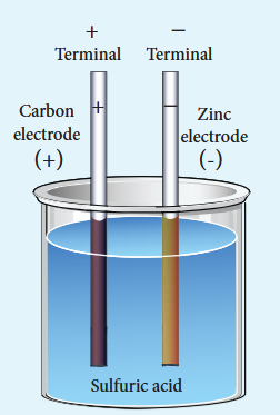
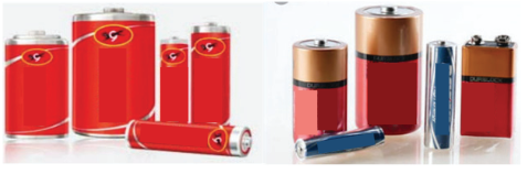
produces potential difference across its terminals. This potential difference provides the energy to move the electrons through the circuit. Commercially available electric cells and batteries are shown in Figure 2.18.
2.4.1 Electromotive force and internal resistance#
A battery or cell is called a source of electromotive force (emf). The term ‘electromotive force’ is a misnomer since it does not really refer to a force but describes a potential difference in volts. The emf of a battery or cell is the voltage provided by the battery when no current flows in the external circuit. It is shown in Figure 2.19. Electromotive force determines the amount of work a battery or cell has to do
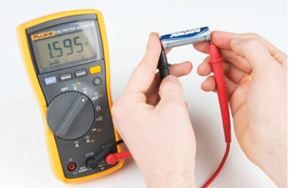
move a certain amount of charge around the circuit. It is denoted by the symbol $\epsilon$ . An ideal battery has zero internal resistance and the potential difference (terminal voltage) across the battery equals to its emf. In reality, the battery is made of electrodes and electrolyte, there is resistance to the flow of charges within the battery. This resistance is called internal resistance $r$ . For a real battery, the terminal voltage is not equal to the emf of the battery. A freshly prepared cell has low internal resistance and it increases with ageing.
2.4.2 Determination of internal resistance#
The circuit connections are made as shown in Figure 2.20.
A battery or cell is called a source of electromotive force (emf). The term ’electromotive force’ is a misnomer since it does not really refer to a force but describes a potential difference in volts. The emf of a battery or cell is the voltage provided by the battery when no current flows in the external circuit. It is shown in Figure 2.19.
Electromotive force determines the amount of work a battery or cell has to do
The emf of cell $\epsilon$ is measured by connecting a high resistance voltmeter across it without connecting the external resistance $R$ as shown in Figure 2.20(a). Since the voltmeter draws very little current for deflection, the circuit may be considered as open. Hence the voltmeter reading gives the emf of the cell. Then, external resistance $R$ is included in the circuit and current $I$ is established in the circuit. The potential difference across
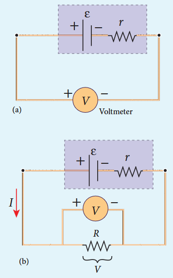
R is equal to the potential difference across the cell (V) as shown in Figure 2.20(b).
The potential drop across the resistor $R$ is
$$V = IR \quad (2.35)$$Due to internal resistance $r$ of the cell, the voltmeter reads a value $V$ , which is less than the emf of cell $\epsilon$ . It is because, certain amount of voltage $(Ir)$ has dropped across the internal resistance $r$ .
$${\mathrm{Then}}\qquad V=\epsilon-{\mathrm{Ir}}$$$$Ir = \epsilon -V \quad (2.36)$$Dividing equation (2.36) by equation (2.35), we get
$$\frac{Ir}{IR} = \frac{\epsilon - V}{V}$$$$r = \left[\frac{\epsilon - V}{V}\right]R \quad (2.37)$$Since $\epsilon$ , $V$ and $R$ are known, internal resistance $r$ can be determined. We can also find the total current that flows in the circuit.
Due to this internal resistance, the power delivered to the circuit is not equal to power rating mentioned in the battery. For a battery of emf $\epsilon$ , with an internal resistance $r$ , the power delivered to the circuit of resistance $R$ is given by
$$P = I\epsilon = I(V + Ir)\quad (\mathrm{from~equation~2.36})$$Here $V$ is the voltage drop across the resistance $R$ and it is equal to $IR$ .
Therefore, $P = I(IR + Ir)$
$$P = I^2 R + I^2 r \quad (2.38)$$Here $I^2 r$ is the power delivered to the internal resistance and $I^2 R$ is the power delivered to the electrical device (here it is the resistance $R$ ). For a good battery, the internal resistance $r$ is very small, then $I^2 r \ll I^2 R$ and almost entire power is delivered to the external resistance.
EXAMPLE 2.17#
A battery has an emf of $12\mathrm{V}$ and connected to a resistor of $3\Omega$ . The current in the circuit is $3.93\mathrm{A}$ . Calculate (a) terminal voltage and the internal resistance of the battery (b) power delivered by the battery and power delivered to the resistor
Solution#
The given values $I = 3.93\mathrm{A}$ , $\epsilon = 12\mathrm{V}$ , $R = 3\Omega$
(a) The terminal voltage of the battery is equal to voltage drop across the resistor $V = IR = 3.93 \times 3 = 11.79 \mathrm{~V}$
The internal resistance of the battery,
$$r = \left|\frac{\epsilon - V}{V}\right|R = \left|\frac{12 - 11.79}{11.79}\right|\times 3 = 0.05\Omega$$(b) The power delivered by the battery $P$ $= I\epsilon = 3.93\times 12 = 47.1\mathrm{W}$
The power delivered to the resistor $= I^{2}R$ $= 46.3\mathrm{W}$
The remaining power $P = (47.1 - 46.3) =$ $0.8\mathrm{W}$ is delivered to the internal resistance and cannot be used to do useful work. (It is equal to $I^{2}r$
2.4.3 Cells in series#
Several cells can be connected to form a battery. In series connection, the negative terminal of one cell is connected to the positive terminal of the second cell, the negative terminal of second cell is connected to the positive terminal of the third cell and so on. The free positive terminal of the first cell and the free negative terminal of the last cell become the terminals of the battery.
Suppose $n$ cells, each of emf $\epsilon$ volts and internal resistance $r$ ohms are connected in series with an external resistance $R$ as shown in Figure 2.21
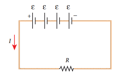
The total emf of the battery $= n\epsilon$
The total resistance in the circuit $= n r + R$
By Ohm’s law, the current in the circuit is
$$I = \frac{\mathrm{totalemf}}{\mathrm{totalresistance}} = \frac{n\epsilon}{nr + R} \quad (2.39)$$Case a If $r< < R$ then,
$$I = \frac{n\epsilon}{R}\approx nI_{1} \quad (2.40)$$where, $I_{1}$ is the current due to a single cell
$$\left(I_{1} = \frac{\epsilon}{R}\right)$$Thus, if $r$ is negligible when compared to $R$ the current supplied by the battery is $n$ times that supplied by a single cell.
$$\mathrm{Case(b)If}r > > R,I = \frac{n\epsilon}{nr}\approx \frac{\epsilon}{r} \quad (2.41)$$It is the current due to a single cell. That is, current due to the whole battery is the same as that due to a single cell and hence there is no advantage in connecting several cells.
Thus series connection of cells is advantageous only when the effective internal resistance of the cells is negligibly small compared with $R$ .
EXAMPLE 2.18#
From the given circuit,
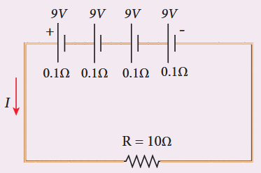
- Equivalent emf of the combination 2) Equivalent internal resistance 3) Total current 4) Potential difference across external resistance 5) Potential difference across each cell
Solution#
i) Equivalent emf of the combination $\epsilon_{eq} = n\epsilon = 4\times 9 = 36\mathrm{V}$
ii) Equivalent internal resistance $r_{eq} = nr$ $= 4\times 0.1 = 0.4\Omega$
iii) Total current $I = \frac{n\epsilon}{R + nr}$
$$= \frac{4\times 9}{10 + (4\times 0.1)}$$$$= \frac{4\times 9}{10 + 0.4} = \frac{36}{10.4}$$$$I = 3.46\mathrm{A}$$iv) Potential difference across external resistance $V = IR = 3.46\times 10 = 34.6\mathrm{V}$ The remaining $1.4\mathrm{V}$ is dropped across the internal resistances of cells.
v) Potential difference across each cell $\frac{V}{n} = \frac{34.6}{4} = 8.65\mathrm{V}$
2.4.4 Cells in parallel#
In parallel connection all the positive terminals of the cells are connected to one point and all the negative terminals to a second point. These two points form the positive and negative terminals of the battery.
Let $n$ cells be connected in parallel between the points A and B and a resistance $R$ is connected between the points A and B as shown in Figure 2.22. Let $\epsilon$ be the emf and $r$ the internal resistance of each cell.
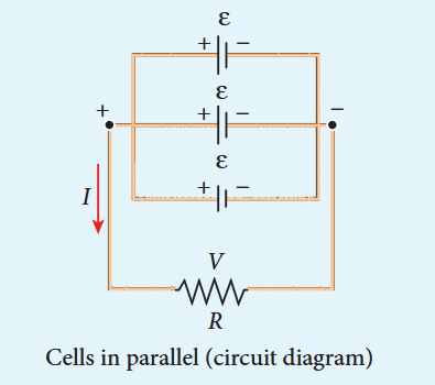
The equivalent internal resistance of the battery is $\frac{1}{r_{eq}} = \frac{1}{r} +\frac{1}{r} +\dots \frac{1}{r} (n\mathrm{terms}) = \frac{n}{r}$ . So $r_{eq} = \frac{r}{n}$ and the total resistance in the circuit is $R + \frac{r}{n}$ . The total emf is the potential difference between the points A and B, which is equal to $\epsilon$ . The current in the circuit is given by
$$I = \frac{\epsilon}{\frac{r}{n} + R}$$$$I = \frac{n\epsilon}{r + nR} \quad (2.42)$$$$\mathrm{Case~}(a)\mathrm{~If~}r > > R,I = \frac{n\epsilon}{r} = nI_{1} \quad (2.43)$$where $I_{1}$ is the current due to a single cell $\left(\frac{\epsilon}{r}\right)$ when $R$ is negligible. Thus, the current through the external resistance due to the whole battery is $n$ times the current due to a single cell.
$$\mathrm{Case~}(b)\mathrm{~If~}r< < R,I = \frac{\epsilon}{R} \quad (2.44)$$The above equation implies that current due to the whole battery is the same as that due to a single cell. Hence it is advantageous to connect cells in parallel when the external resistance is very small compared to the internal resistance of the cells.
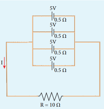
EXAMPLE 2.19#
For the given circuit
Find
i) Equivalent emf ii) Equivalent internal resistance iii) Total current (I) iv) Potential difference across each cell v) Current from each cell
Solution#
i) Equivalent emf $\epsilon_{eq} = 5 \mathrm{~V}$ ii) Equivalent internal resistance,
$$\mathrm{R_{eq}} = \frac{r}{n} = \frac{0.5}{4} = 0.125\Omega$$iii) total current, $I = \frac{\epsilon}{R + \frac{r}{n}}$
$$I = \frac{5}{10 + 0.125} = \frac{5}{10.125}$$I $\approx 0.5 \mathrm{~A}$
iv) Potential difference across each cell
$$\mathrm{V} = \mathrm{IR} = 0.5\times 10 = 5\mathrm{V}$$v) Current from each cell, $I^{\prime} = \frac{I}{n}$
$$I^{\prime} = \frac{0.5}{4} = 0.125\mathrm{A}$$2.5#
KIRCHHOFF’S RULES#
Ohm’s law is useful only for simple circuits. For more complex circuits, Kirchhoff’s rules can be used to find current and voltage. There are two generalized rules: i) Kirchhoff’s current rule ii) Kirchhoff’s voltage rule.
2.5.1 Kirchhoff’s first rule (Current rule or Junction rule)#
It states that the algebraic sum of the currents at any junction of a circuit is zero. It is a statement of law of conservation of electric charge. The charges that enter a given junction in a circuit must leave that junction since charge cannot build up or disappear at a junction. By convention, current entering the junction is taken as positive and current leaving the junction is taken as negative.
2.5.2 Kirchhoff’s Second rule (Voltage rule or Loop rule)
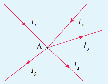
Applying this law to the junction A in Figure 2.23
$$I_{1} + I_{2} - I_{3} - I_{4} - I_{5} = 0$$$$(\mathrm{or})$$$$I_{1} + I_{2} = I_{3} + I_{4} + I_{5}$$EXAMPLE 2.20#
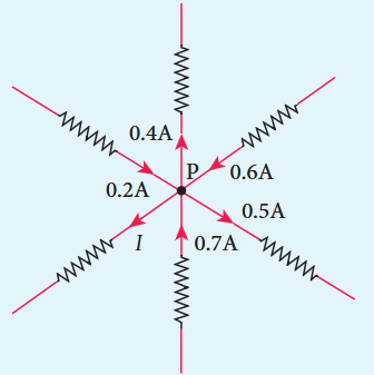
For the given circuit find the value of $I$ .
Solution#
Applying Kirchhoff’s rule to the point P in the circuit,
The arrows pointing towards P are positive and away from P are negative.
$$0.2\mathrm{A} - 0.4\mathrm{A} + 0.6\mathrm{A} - 0.5\mathrm{A} +$$$$0.7\mathrm{A} - I = 0$$$$1.5\mathrm{A} - 0.9\mathrm{A} - I = 0$$$$0.6\mathrm{A} - I = 0$$2.5.2 Kirchhoff’s Second rule (Voltage rule or Loop rule)#
It states that in a closed circuit the algebraic sum of the products of the current and resistance of each part of the circuit is equal to the total emf included in the circuit. This rule follows from the law of conservation of energy for an isolated system (The energy supplied by the emf sources is equal to the sum of the energy delivered to all resistors). The product of current and resistance is taken as positive when the direction of the current is followed. Suppose if the direction of current is opposite to the direction of the loop, then product of current and voltage across the resistor is negative. It is shown in Figure 2.24 (a) and (b). The emf is considered positive when proceeding from the negative to the positive terminal of the cell. It is shown in Figure 2.24 (c) and (d).
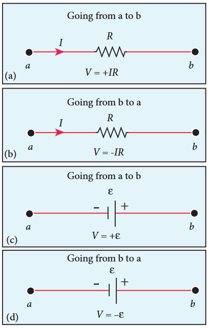
Kirkhoff voltage rule has to be applied only when all currents in the circuit reach a steady state condition (the current in various branches are constant).
EXAMPLE 2.21#
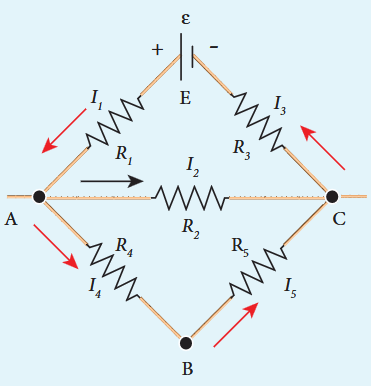
The following figure shows a complex network of conductors which can be divided into two closed loops like EACE and ABCA. Apply Kirchhoff’s voltage rule (KVR),
Solution#
Thus applying Kirchhoff’s second law to the closed loop EACE
$$I_{1}R_{1} + I_{2}R_{2} + I_{3}R_{3} = \epsilon$$and for the closed loop ABCA
$$I_{4}R_{4} + I_{5}R_{5} - I_{2}R_{2} = 0$$EXAMPLE 2.22#
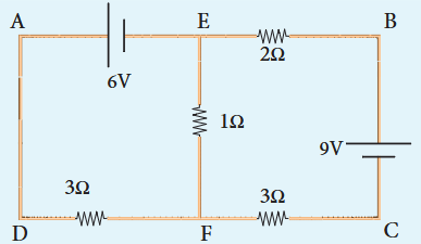
Calculate the current that flows in the 1 $\Omega$ resistor in the following circuit.
Solution#
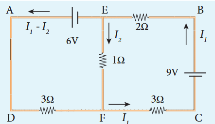
We can denote the current that flows from 9V battery as $I_{1}$ and it splits up into $I_{2}$ and $(I_{1} - I_{2})$ at the junction E according Kirchhoff’s current rule (KCR).
Now consider the loop EFCBE and apply KVR, we get
$$I_{1}I_{2} + 3I_{1} + 2I_{1} = 9$$$$5I_{1} + I_{2} = 9$$Applying KVR to the loop EADFE, we get
$$3(I_{1} - I_{2}) - 1I_{2} = 6$$$$3I_{1} - 4I_{2} = 6$$Solving equation (1) and (2), we get
$$I_{1} = 1.83\mathrm{A}\mathrm{and}I_{2} = -0.13\mathrm{A}$$It implies that the current in the 1 ohm resistor flows from F to E.
2.5.3 Wheatstone’s bridge#
An important application of Kirchhoff’s rules is the Wheatstone’s bridge. It is used to compare resistances and in determining the unknown resistance in electrical network. The bridge consists of four resistances $P$ , $Q$ , $R$ and $S$ connected as shown in Figure 2.25. A galvanometer $G$ is connected between the points $B$ and $D$ . The battery is connected between the points $A$ and $C$ . The current
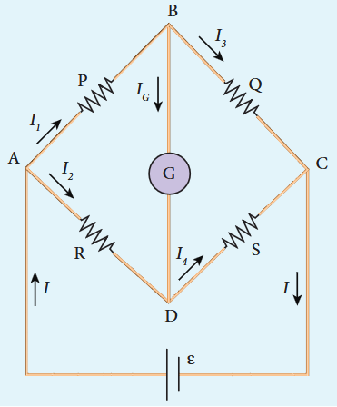
Figure 2.25 Wheatstone’s bridge
through the galvanometer is $I_{G}$ and its resistance is $G$ .
Applying Kirchhoff’s current rule to junction $B$ and $D$ respectively.
$$\begin{array}{l}I_1 - I_G - I_3 = 0\\ I_2 + I_G - I_4 = 0 \end{array} \quad (2.45)$$Applying Kirchhoff’s voltage rule to loop ABDA,
$$I_{1}P + I_{G}G - I_{2}R = 0 \quad (2.47)$$Applying Kirchhoff’s voltage rule to loop ABCDA,
$$I_{1}P + I_{3}Q - I_{4}S - I_{2}R = 0 \quad (2.48)$$When the points $B$ and $D$ are at the same potential, the bridge is said to be balanced. As there is no potential difference between $B$ and $D$ , no current flows through galvanometer $(I_{G} = 0)$ . Substituting $I_{G} = 0$ in equation (2.45), (2.46) and (2.47), we get
$$I_{1} = I_{3} \quad (2.49)$$$$\begin{array}{l}I_{2} = I_{4} \\ I_{1}P = I_{2}R \end{array} \quad (2.50)$$Using equation (2.51) in equation (2.48)
$$I_{3}Q = I_{4}S \quad (2.52)$$Dividing equation (2.52) by equation (2.51), we get
$$\frac{P}{Q} = \frac{R}{S} \quad (2.53)$$This is the condition for bridge balance. Only under this condition, galvanometer shows null deflection. Suppose we know the values of two adjacent resistances, the other two resistances can be compared. If three of the resistances are known, the value of unknown resistance (fourth one) can be determined.
A galvanometer is an instrument used for detecting and measuring even very small electric currents. It is extensively useful to compare the potential difference between various parts of the circuit.
EXAMPLE 2.23#
In a Wheatstone’s bridge $P = 100 \Omega$ , $Q = 1000 \Omega$ and $R = 40 \Omega$ . If the galvanometer shows zero deflection, determine the value of $S$ .
Solution#
\[ \frac{P}{Q} = \frac{R}{S} \]\[ S = \frac{Q}{P} \times R \]\[ S = \frac{1000}{100} \times 40 = 400 \, \Omega \]EXAMPLE 2.24#
What is the value of \( x \) when the Wheatstone’s network is balanced?
\( P = 500 \, \Omega \), \( Q = 800 \, \Omega \), \( R = x + 400 \), \( S = 1000 \, \Omega \)
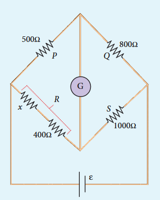
Solution#
\[ \frac{P}{Q} = \frac{R}{S}, \text{ when the network is balanced} \]\[ \frac{500}{800} = \frac{x + 400}{1000} \]\[ x + 400 = \frac{5}{8} \times 1000 \]\[ x + 400 = 625 \]\[ x = 625 - 400 \]\[ x = 225 \, \Omega \]2.5.4 Meter bridge#
The meter bridge is another form of Wheatstone’s bridge. It consists of a uniform wire of manganin AB of one meter length. This wire is stretched along a metre scale on a wooden board between two copper strips C and D. Between these two copper strips another copper strip E is mounted to enclose two gaps \( \mathrm{G}_{1} \) and \( \mathrm{G}_{2} \) as shown in Figure 2.26.
An unknown resistance \( P \) is connected in \( \mathrm{G}_{1} \) and a standard resistance \( Q \) is connected in \( \mathrm{G}_{2} \). A jockey (conducting wire - contact maker) is connected to the terminal E on the central copper strip through a galvanometer (G) and a high resistance (HR). The exact position of jockey on the wire can be read on the scale. A Lechlanche cell and a key (K) are connected between the ends of the bridge wire.
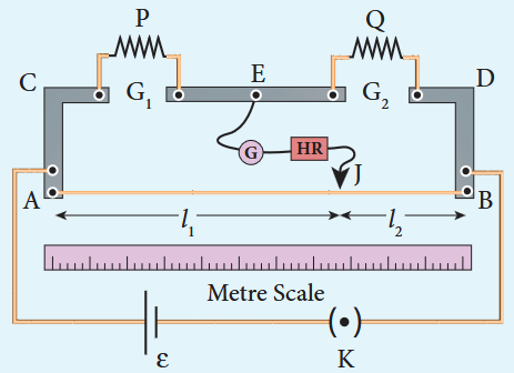
The position of the jockey on the wire is adjusted so that the galvanometer shows zero deflection. Let the position of jockey at the wire be at J. The resistances corresponding to AJ and JB of the bridge wire form the resistances $R$ and $S$ of the Wheatstone’s bridge. Then for the bridge balance
$$\frac{P}{Q} = \frac{R}{S} = \frac{r.AJ}{r.JB} \quad (2.54)$$where $r$ is the resistance per unit length of wire.
$$\frac{P}{Q} = \frac{AJ}{JB} = \frac{l_1}{l_2} \quad (2.55)$$$$P = Q\frac{l_1}{l_2} \quad (2.56)$$The bridge wire is soldered at the ends of the copper strips. Due to imperfect contact, some resistance might be introduced at the contact. These are called end resistances. This error can be eliminated, if another set of readings is taken with $P$ and $Q$ interchanged and the average value of $P$ is found.
To find the specific resistance of the material of the wire in the coil $\mathrm{P}$ the radius $a$ and length $l$ of the wire are measured. The specific resistance or resistivity $\rho$ can be calculated using the relation.
$$\mathrm{Resistance} = \rho \frac{l}{A}$$By rearranging the above equation, we get
$$\rho = \mathrm{Resistance}\times \frac{A}{l} \quad (2.57)$$If $P$ is the unknown resistance equation (2.57) becomes,
$$\rho = P\frac{\pi a^2}{l}$$EXAMPLE 2.25#
In a meter bridge experiment with a standard resistance of $15\Omega$ in the right gap, the ratio of balancing length is 3:2. Find the value of the other resistance.
Solution#
$$Q = 15\Omega ,\qquad l_{1}:l_{2} = 3:2$$$$\frac{l_1}{l_2} = \frac{3}{2}$$\[ \frac{P}{Q} = \frac{l_1}{l_2} \]\[ P = Q \frac{l_1}{l_2} \]\[ P = 15 \times \frac{3}{2} = 22.5 \, \Omega \]EXAMPLE 2.26#
In a meter bridge experiment, the value of resistance in the resistance box connected in the right gap is $10\Omega$ . The balancing length is $l_{1} = 55\mathrm{cm}$ . Find the value of unknown resistance.
Solution#
$$Q = 10\Omega$$$$\frac{P}{Q} = \frac{l_1}{100 - l_1} = \frac{l_1}{l_2}$$$$P = Q\times \frac{l_1}{100 - l_1}$$$$P = \frac{10\times 55}{100 - 55}$$$$P = \frac{550}{45} = 12.2\Omega$$2.5.5 Potentiometer#
Potentiometer is used for the accurate measurement of potential differences, current and resistances. It consists of ten meter long uniform wire of manganin or constantan stretched in parallel rows each of 1 meter length, on a wooden board. The two free ends A and B are brought to the same side and fixed to copper strips with binding screws. A meter scale is fixed parallel to the wire. A jockey is provided for making contact.
The principle of the potentiometer is illustrated in Figure 2.27. A steady current is maintained across the wire CD by a battery $B t$ .
The battery, key and the potentiometer wire connected in series form the primary circuit. The positive terminal of a primary cell of emf $\epsilon$ is connected to the point C and negative terminal is connected to the jockey through a galvanometer G and a high resistance HR. This forms the secondary circuit.
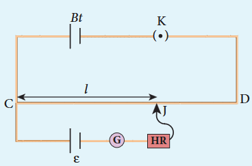
Let the contact be made at any point J on the wire by jockey. If the potential difference across CJ is equal to the emf of the cell $\epsilon$ , then no current will flow through the galvanometer and it will show zero deflection. CJ is the balancing length $l$ . The potential difference across CJ is equal to $l r l$ where $I$ is the current flowing through the wire and $r$ is the resistance per unit length of the wire.
$$\mathrm{Hence} \epsilon = I r l \quad (2.58)$$Since $I$ and $r$ are constants, $\epsilon \propto l$ . The emf of the cell is directly proportional to the balancing length.
2.5.6 Comparison of emf of two cells with a potentiometer#
To compare the emf of two cells, the circuit connections are made as shown in Figure 2.28. Potentiometer wire CD is connected to a battery $B t$ and a key K in
The end C of the wire is connected to the terminal M of a DPDT (Double Pole Double Throw) switch and the other terminal N is connected to a jockey through a galvanometer G and a high resistance HR. The cells whose emf \( \epsilon_{1} \) and \( \epsilon_{2} \) are to be compared are connected to the terminals \( \mathbf{M}_{1}, \mathbf{N}_{1} \) and \( \mathbf{M}_{2}, \mathbf{N}_{2} \) of the DPDT switch. The positive terminals of \( Bt \), \( \epsilon_{1} \) and \( \epsilon_{2} \) should be connected to the same end C.
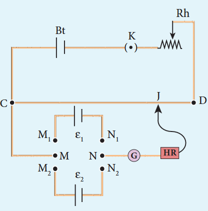
The DPDT switch is pressed towards \( \mathbf{M}_{1} \mathbf{N}_{1} \) so that cell \( \epsilon_{1} \) is included in the secondary circuit and the balancing length \( l_{1} \) is found by adjusting the jockey for zero deflection. Then the second cell \( \epsilon_{2} \) is included in the circuit and the balancing length \( l_{2} \) is determined. Let \( r \) be the resistance per unit length of the potentiometer wire and \( I \) be the current flowing through the wire.
$$\begin{array}{l}\mathrm{we~have}\quad \epsilon_{1} = I r l_{1}\\ \epsilon_{2} = I r l_{2} \end{array} \quad (2.60)$$By dividing equation (2.59) by (2.60)
$$\frac{\epsilon_{1}}{\epsilon_{2}} = \frac{l_{1}}{l_{2}} \quad (2.61)$$By including a rheostat (Rh) in the primary circuit, the experiment can be repeated several times by changing the current flowing through it.
2.5.7 Measurement of internal resistance of a cell by potentiometer#
To measure the internal resistance of a cell, the circuit connections are made as shown in Figure 2.29. The end C of the potentiometer wire is connected to the positive terminal of the battery Bt and the negative terminal of the battery is connected to the end D through a key $\mathrm{K}_{1}$ . This forms the primary circuit.
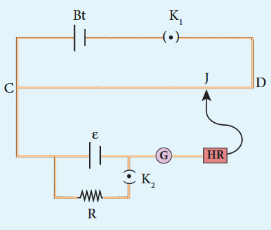
The positive terminal of the cell of emf \( \epsilon \) whose internal resistance is to be determined is also connected to the end C of the wire. The negative terminal of the cell \( \epsilon \) is connected to a jockey through a galvanometer and a high resistance. A resistance box R and key \( \mathrm{K}_{2} \) are connected across the cell \( \epsilon \). With \( \mathrm{K}_{2} \) open, the balancing point J is obtained and the balancing length \( \mathrm{CJ} = l_{1} \) is measured. Since the cell is in open circuit, its emf is
$$\epsilon \propto l_{1} \quad (2.62)$$A suitable resistance (say, $10\Omega$ ) is included in the resistance box and key $\mathrm{K}_{2}$ is closed. Let r be the internal resistance of the cell. The current passing through the cell and the resistance R is given by
$$I = \frac{\epsilon}{R + r}$$The potential difference across R is
$$V = \frac{\epsilon R}{R + r}$$When this potential difference is balanced on the potentiometer wire, let $l_{2}$ be the balancing length.
$$\mathrm{Then}\frac{\epsilon R}{R + r}\propto l_{2} \quad (2.63)$$From equations (2.62) and (2.63)
$$\begin{array}{l}\frac{R + r}{R} = \frac{l_1}{l_2}\\ 1 + \frac{r}{R} = \frac{l_1}{l_2};\\ r = R\left[\frac{l_1}{l_2} -1\right]\\ \therefore r = R\left(\frac{l_1 - l_2}{l_2}\right) \end{array} \quad (2.65)$$Substituting the values of the $R$ $l_{1}$ and $l_{2}$ , the internal resistance of the cell is determined. The experiment can be repeated for different values of $R$ . It is found that the internal resistance of the cell is not constant but increases with increase of external resistance connected across its terminals.
2.6#
HEATING EFFECT OF ELECTRIC CURRENT#
When current flows through a resistor, some of the electrical energy delivered to the resistor is converted into heat energy and it is dissipated. This heating effect of current is known as Joule’s heating effect. Just as current produces thermal energy, thermal energy may also be suitably used to produce an electromotive force. This is known as thermoelectric effect.
2.6.1 Joule’s law#
If a current $I$ flows through a conductor kept across a potential difference $V$ for a time $t$ , the work done or the electric potential energy spent is
$$W = VI t \quad (2.66)$$In the absence of any other external effect, this energy is spent in heating the conductor. The amount of heat $(H)$ produced is
$$H = VI t \quad (2.67)$$For a resistance $R$
$$H = PRt \quad (2.68)$$This relation was experimentally verified by Joule and is known as Joule’s law of heating. It states that the heat developed in an electrical circuit due to the flow of current varies directly as
(i) the square of the current (ii) the resistance of the circuit and (iii) the time of flow.
EXAMPLE 2.27#
Find the heat energy produced in a resistance of $10\Omega$ when 5 A current flows through it for 5 minutes.
Solution#
$$R = 10\Omega ,I = 5\mathrm{A},t = 5\mathrm{minutes} = 5\times 60\mathrm{s}$$$$H = I^2 Rt$$$$= 5^2\times 10\times 5\times 60$$$$= 25\times 10\times 300$$$$= 25\times 3000$$$$= 75000\mathrm{J}(\mathrm{or})75\mathrm{kJ}$$2.6.2 Application of Joule’s heating effect#
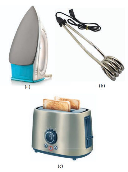
1.Electric heaters#
Electric iron, electric heater, electric toaster shown in Figure 2.30 are some of the home appliances that utilize the heating effect of current. In these appliances, the heating elements are made of nichrome, an alloy of nickel and chromium. Nichrome has a high specific resistance and can be heated to very high temperatures without oxidation.
EXAMPLE 2.28#
An electric heater of resistance $10\Omega$ connected to $220\mathrm{V}$ power supply is immersed in the water of $1\mathrm{kg}$ . How long the electrical heater has to be switched on to increase its temperature from $30^{\circ}C$ to $60^{\circ}C$ . (Specific heat capacity of water is $s = 4200\mathrm{Jkg^{- 1}K^{- 1}}$ )
Solution#
According to Joule’s heating law $H = I^2 Rt$ The current passed through the electrical heater $= \frac{220V}{10\Omega} = 22A$ Heat produced in one second by the electrical heater $H = PR$
Heat produced in one second $H = (22)^2 \times 10 = 4840 \mathrm{~J} = 4.84 \mathrm{~kJ}$ . In fact the power rating of this electrical heater is $4.84 \mathrm{~kW}$ .
The amount of heat energy to increase the temperature of $1 \mathrm{~kg}$ water from $30^{\circ} \mathrm{C}$ to $60^{\circ} \mathrm{C}$ is
$$Q = ms\Delta T\quad (\mathrm{Refer~XI~physics~vol~2,~unit~8})$$$$\mathrm{Here~}m = 1\mathrm{kg},$$$$s = 4200\mathrm{~J~kg}^{-1}\mathrm{~K}^{-1},$$$$\Delta T = 30\mathrm{~K},$$$$\mathrm{so~}Q = 1\times 4200\times 30 = 126\mathrm{~kJ~}$$The time required to produce this heat energy $t = \frac{Q}{I^2 R} = \frac{126 \times 10^3}{4840} \approx 26.03 \mathrm{~s}$
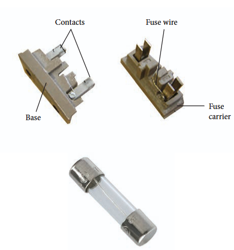
2. Electric fuses#
Fuses as shown in Figure 2.31, are connected in series in a circuit to protect the electric devices from the heat developed by the passage of excessive current. It is a short length of a wire made of a low melting point material. It melts and breaks the circuit if current exceeds a certain value. An alloy of lead - tin is used for fuses when current rating is below 15 A and when current rating is above 15 A, copper fuse wires are used.
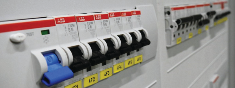
The only disadvantage with the above fuses is that once fuse wire is burnt due to excessive current, they need to be replaced. Nowadays in houses, circuit breakers
(trippers) are also used instead of fuses. Whenever there is an excessive current produced due to faulty wire connection, the circuit breaker switch opens. After repairing the faulty connection, we can close the circuit breaker switch. It is shown in the Figure 2.32.
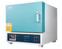
3. Electric furnace#
Furnaces as shown in Figure 2.33 are used to manufacture a large number of technologically important materials such as steel, silicon carbide, quartz, gallium arsenide, etc. To produce temperatures up to $1500^{\circ} \mathrm{C}$ , molybdenum- nichrome wire wound on a silica tube is used. Carbon arc furnaces produce temperatures up to $3000^{\circ} \mathrm{C}$ .
2.7.1 Seebeck effect
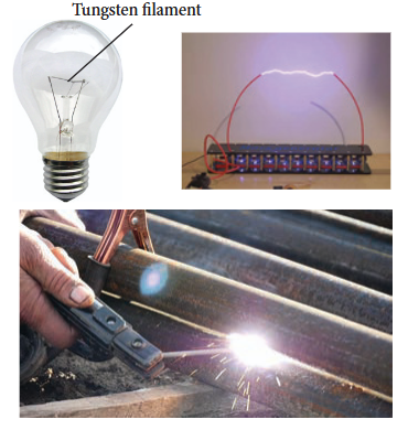
4. Electrical lamp#
It consists of a tungsten filament (melting point $3380^{\circ}\mathrm{C}$ ) kept inside a glass bulb and heated to incandescence by current. In incandescent electric lamps only about $5%$ of electrical energy is converted into light and the rest is wasted as heat. Electric discharge lamps, electric welding and electric arc also utilize the heating effect of current as shown in Figure 2.34.
2.7 THERMOELECTRIC EFFECT#
Conversion of temperature differences into electrical voltage and vice versa is known as thermoelectric effect. A thermoelectric device generates voltage when there is a temperature difference on each side. If a voltage is applied, it generates a temperature difference.
2.7.1 Seebeck effect#
Seebeck discovered that in a closed circuit consisting of two dissimilar metals, when the junctions are maintained at different temperatures an emf (potential difference) is developed. The current that flows due to the emf developed is called thermoelectric current. The two dissimilar metals connected to form two junctions is known as thermocouple (Figure 2.35).
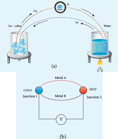
If the hot and cold junctions are interchanged, the direction of current also reverses. Hence the effect is reversible.
The magnitude of the emf developed in a thermocouple depends on (i) the nature of the metals forming the couple and (ii) the temperature difference between the junctions.
Applications of Seebeck effect#
Seebeck effect is used in thermoelectric generators (Seebeck generators).These thermoelectric generators are used in power plants to convert waste heat into electricity.
This effect is utilized in automobiles as automotive thermoelectric generators for increasing fuel efficiency.
Seebeck effect is used in thermocouples and thermopiles to measure the temperature difference between the two objects.
2.7.2 Peltier effect#
In 1834, Peltier discovered that when an electric current is passed through a circuit of a thermocouple, heat is evolved at one junction and absorbed at the other junction. This is known as Peltier effect.
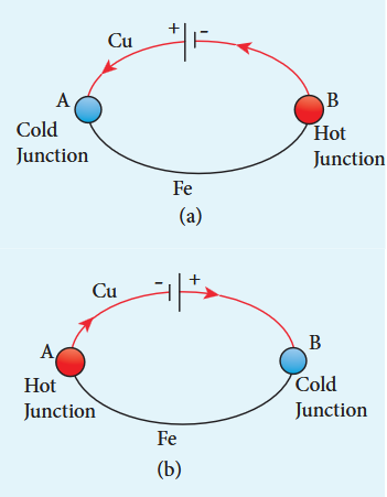
In the Cu- Fe thermocouple the junctions A and B are maintained at the same temperature. Let a current from a battery flow through the thermocouple (Figure 2.36 (a)). At the junction A, where the current flows from Cu to Fe, heat is absorbed and the junction A becomes cold. At the junction B, where the current flows from Fe to Cu heat is liberated and it becomes hot. When the direction of current is reversed, junction A
gets heated and junction B gets cooled as shown in the Figure 2.36(b). Hence Peltier effect is reversible.
2.7.3 Thomson effect#
Thomson showed that if two points in a conductor are at different temperatures, the density of electrons at these points will differ and as a result the potential difference is created between these points. Thomson effect is also reversible.
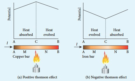
If current is passed through a copper bar AB which is heated at the middle point C, the point C will be at higher potential. This indicates that the heat is absorbed along AC and evolved along CB of the conductor as shown in Figure 2.37(a). Thus heat is transferred due to the current flow in the direction of the current. It is called positive Thomson effect. Similar effect is observed in metals like silver, zinc, and cadmium.
When the copper bar is replaced by an iron bar, heat is evolved along CA and absorbed along BC. Thus heat is transferred due to the current flow in the direction opposite to the direction of current. It is called negative Thomson effect as shown in the Figure 2.37(b). Similar effect is observed in metals like platinum, nickel, cobalt, and mercury.
SUMMARY#
- The current, \( I \) flowing in a conductor \( I = \frac{dQ}{dt} \), where \( dQ \) is the charge that flows through a cross-section in a time interval \( dt \). SI unit of current is ampere (A).
The current density \( J \) in a conductor is the current flowing per unit area. \( J = \frac{I}{A} \)
Current is a scalar but current density is a vector.
The general form of Ohm’s law \( \vec{J} = \sigma \vec{E} \)
Practical form of Ohm’s law states that \( V \propto I \), or \( V = IR \) where \( I \) is the current and \( R \) is the resistance, \( V \) potential difference between ends of the conductor.
The resistance \( R \) of a conductor is \( R = \frac{V}{I} \). SI unit of resistance is ohm (\( \Omega \)) and
The resistance of a conductor \( R = \rho \frac{l}{A} \) where \( l \) is length of the conductor and \( A \) is its area of cross section.
The resistivity of a material determines how much resistance it offers to the flow of current.
The equivalent resistance (\( R_s \)) of several resistances (\( R_1, R_2, R_3, \ldots \)) connected in series is \( R_s = R_1 + R_2 + R_3 + \ldots \)
The equivalent resistance (\( R_p \)) of several resistances (\( R_1, R_2, R_3, \ldots \)) connected in parallel is
Kirchhoff’s first rule (Current rule or junction rule): The algebraic sum of the currents at any junction is zero.
Kirchhoff’s second rule (Voltage rule or loop rule): In a closed circuit the algebraic sum of the products of the current and resistance of each part of the circuit is equal to the total emf included in the circuit.
Electric power is the rate at which electric energy is delivered.
If a current \( I \) flows across a potential difference \( V \), the power delivered to the circuit is \( P = IV \).
In a resistor \( R \), the electrical power converted to heat is \( P = I^2R = \frac{V^2}{R} \)
The energy equivalent of one kilowatt-hour (kWh) is \( 1 \text{ kWh} = 3.6 \times 10^6 \text{ J} \).
Metre bridge is one form of Wheatstone’s network.
Potentiometer is used to compare emf of cells.
Joule’s law of heating is \( H = VIt \) (or) \( H = I^2Rt \).
Multiple Choice Questions#
- The following graph shows current versus voltage values of some unknown conductor. What is the resistance of this conductor?
(a) 2 ohm (b) 4 ohm (c) 8 ohm (d) 1 ohm
- A wire of resistance 2 ohms per meter is bent to form a circle of radius 1m. The equivalent resistance between its two diametrically opposite points, A and B as shown in the figure is
(a) $\pi \Omega$ (c) $\frac{\pi}{2}\Omega$ (c) $2\pi \Omega$ (d) $\frac{\pi}{4}\Omega$
- A toaster operating at $240\mathrm{V}$ has a resistance of $120\Omega$ . Its power is
a) $400\mathrm{W}$ b) $2\mathrm{W}$ c) $480\mathrm{W}$ d) $240\mathrm{W}$
- A carbon resistor of $(47\pm 4.7)\mathrm{k}\Omega$ to be marked with rings of different colours for its identification. The colour code sequence will be
a) Yellow - Green - Violet - Gold b) Yellow - Violet - Orange - Silver c) Violet - Yellow - Orange - Silver d) Green - Orange - Violet - Gold
- What is the value of resistance of the following resistor?
(a) $100\mathrm{k}\Omega$ (b) $10\mathrm{k}\Omega$ (c) $1\mathrm{k}\Omega$ (d) $1000\mathrm{k}\Omega$
- Two wires of A and B with circular cross section are made up of the same material with equal lengths. Suppose $R_{A} = 3R_{B}$ , then what is the ratio of radius of wire A to that of B?
(a) 3 (b) $\sqrt{3}$ (c) $\frac{1}{\sqrt{3}}$ (d) $\frac{1}{3}$
- A wire connected to a power supply of $230\mathrm{V}$ has power dissipation $P_{1}$ . Suppose the wire is cut into two equal pieces and connected parallel to the same power supply. In this case power dissipation is $P_{2}$ . The ratio $\frac{P_{2}}{P_{1}}$ is
(a) 1 (b) 2
(c) 3 (d) 4
- In India electricity is supplied for domestic use at $220\mathrm{V}$ . It is supplied at $110\mathrm{V}$ in USA. If the resistance of a $60\mathrm{W}$ bulb for use in India is $R$ , the resistance of a $60\mathrm{W}$ bulb for use in USA will be
(a) $R$ (b) $2R$ (c) $\frac{R}{4}$ (d) $\frac{R}{2}$
- In a large building, there are 15 bulbs of $40\mathrm{W}$ , 5 bulbs of $100\mathrm{W}$ , 5 fans of $80\mathrm{W}$ and 1 heater of $1\mathrm{kW}$ are connected. The voltage of electric mains is $220\mathrm{V}$ . The maximum capacity of the main fuse of the building will be (IIT-JEE 2014)
(a) 14 A (b) 8 A (c) 10 A (d) 12 A
- There is a current of $1.0\mathrm{A}$ in the circuit shown below. What is the resistance of $P$ ?
a) $1.5\Omega$ b) $2.5\Omega$ c) $3.5\Omega$ d) $4.5\Omega$
- What is the current drawn out from the battery?
a) 1A b) 2A c) 3A d) 4A
- The temperature coefficient of resistance of a wire is $0.00125\mathrm{per}^{\circ}\mathrm{C}$ . At $20^{\circ}\mathrm{C}$ , its resistance is $1\Omega$ . The resistance of the wire will be $2\Omega$ at
a) $800^{\circ}\mathrm{C}$ b) $700^{\circ}\mathrm{C}$ c) $850^{\circ}\mathrm{C}$ d) $820^{\circ}\mathrm{C}$
- The internal resistance of a $2.1\mathrm{V}$ cell which gives a current of $0.2\mathrm{A}$ through a resistance of $10\Omega$ is
a) $0.2\Omega$ b) $0.5\Omega$ c) $0.8\Omega$ d) $1.0\Omega$
- A piece of copper and another of germanium are cooled from room temperature to $80\mathrm{K}$ . The resistance of
a) each of them increases b) each of them decreases c) copper increases and germanium decreases d) copper decreases and germanium increases
- In Joule’s heating law, when $R$ and $t$ are constant, if the $H$ is taken along the $y$ axis and $P$ along the $x$ axis, the graph is
a) straight line b) parabola c) circle d) ellipse
Answers#
- a
- a
- c
- b
- a
- c
- d
- c
- d
- c
- a
- d
- b
- d
- a
II Short Answer Questions#
Why current is a scalar?
Define current density.
Distinguish between drift velocity and mobility.
State microscopic form of Ohm’s law.
State macroscopic form of Ohm’s law.
What are ohmic and non ohmic devices?
Define electrical resistivity.
Define temperature coefficient of resistance.
Write a short note on superconductors?
What is electric power and electric energy?
Derive the expression for power $\mathrm{P} = \mathrm{VI}$ in electrical circuit.
Write down the various forms of expression for power in electrical circuit.
State Kirchhoff’s current rule.
State Kirchhoff’s voltage rule.
State the principle of potentiometer.
What do you mean by internal resistance of a cell?
State Joule’s law of heating.
What is Seebeck effect?
What is Thomson effect?
What is Peltier effect?
State the applications of Seebeck effect.
III Long Answer Questions#
Describe the microscopic model of current and obtain microscopic form of Ohm’s law.
Obtain the macroscopic form of Ohm’s law from its microscopic form and discuss its limitation.
Explain the equivalent resistance of a series and parallel resistor network.
Explain the determination of the internal resistance of a cell using voltmeter.
State and explain Kirchhoff’s rules.
Obtain the condition for bridge balance in Wheatstone’s bridge.
Explain the determination of unknown resistance using meter bridge.
How the emf of two cells are compared using potentiometer?
IV Numerical problems#
- The following graphs represent the current versus voltage and voltage versus current for the six conductors A,B,C,D,E and F. Which conductor has least resistance and which has maximum resistance?
Ans: Least: $R_{F} = 0.4\Omega$ , maximum $R_{C} = 2.5\Omega$ 2. Lightning is very good example of natural current. In typical lightning, there is $10^{9}$ J energy transfer across the potential difference of $5\times 10^{7}$ V during a time interval of 0.2 s.
- A copper wire of $10^{- 6}\mathrm{m}^2$ area of cross section, carries a current of 2 A. If the number of free electrons per cubic meter in the wire is $8\times 10^{28}$ , calculate the current density and average drift velocity of electrons.
- The resistance of a nichrome wire at $20^{\circ}\mathrm{C}$ is $10\Omega$ . If its temperature coefficient of resistivity of nichrom is $0.004% \mathrm{C}$ , find the resistance of the wire at boiling point of water. Comment on the result.
As the temperature increases the resistance of the wire also increases.
- The rod given in the figure is made up of two different materials.
Both have square cross sections of $3\mathrm{mm}$ side. The resistivity of the first material is $4\times 10^{- 3}\Omega \mathrm{m}$ and that of second material has resistivity of $5\times 10^{- 3}\Omega \mathrm{m}$ . What is the resistance of rod between its ends?
Ans: $500\Omega$
- Three identical lamps each having a resistance $R$ are connected to the battery of emf $\epsilon$ as shown in the figure.
Suddenly the switch S is closed. (a) Calculate the current in the circuit when S is open and closed (b) What happens to the intensities of the bulbs A,B and C. (c) Calculate the voltage across the three bulbs when S is open and closed (d) Calculate the power delivered to the circuit when S is opened and closed (e) Does the power delivered to the circuit decrease, increase or remain same?
Ans:
| Electrical quantities | Switch S is open | Switch S is closed |
|---|---|---|
| a) Current | $\epsilon/3R$ | $\epsilon/2R$ |
| b) Voltage | $V_A = \epsilon/3$ $V_B = \epsilon/3$ $V_C = \epsilon/3$ | $V_A = \epsilon/2$ $V_B = \epsilon/2$ $V_C = 0$ |
| c) Power | $P_A = \epsilon^2/9R$ $P_B = \epsilon^2/9R$ $P_C = \epsilon^2/9R$ | $P_A = \epsilon^2/4R$ $P_B = \epsilon^2/4R$ $P_C = 0$ Total power increases |
| d) Intensity | All the bulbs glow with equal intensity | The intensities of the bulbs A and B equally increase. Bulb C will not glow since no current pass through it. |
| e) | Increases | |
- An electronics hobbyist is building a radio which requires $150\Omega$ in her circuit. But she has only $220\Omega$ $79\Omega$ and $92\Omega$ resistors available. How can she connect the available resistors to get the desired value of resistance?Ans: Parallel combination of $220\Omega$ and $79\Omega$ in series with $92\Omega$ 8. A cell supplies a current of $0.9\mathrm{A}$ through a $2\Omega$ resistor and a current of $0.3\mathrm{A}$ through a $7\Omega$ resistor. Calculate the internal resistance of the cell.Ans: $0.5\Omega$ 9. Calculate the currents in the following circuit.Ans: $I_{1} = 0.070\mathrm{A}$ $I_{2} = -0.010\mathrm{A}$ and $I_{3} = 0.080\mathrm{A}$ 10. A potentiometer wire has a length of 4 m and resistance of $20\Omega$ . It is connected in series with resistance of $2980\Omega$ and a cell of emf $4\mathrm{V}$ . Calculate the potential gradient along the wire.Ans: Potential $= 0.65\times 10^{- 2}\mathrm{Vm}^{- 1}$ 11. Determine the current flowing through the galvanometer (G) as shown in the figure.
Ans: $\mathrm{I}_{\mathrm{g}} = \frac{1}{11}\mathrm{A}$
- Two cells each of $5\mathrm{V}$ are connected in series with a $8\Omega$ resistor and three parallel resistors of $4\Omega$ $6\Omega$ and $12\Omega$ Draw a circuit diagram for the above arrangement. Calculate i) the current drawn from the cells (ii) current through each resistorAns:
Ans:
i) Current through $8\Omega = 1\mathrm{A}$ ii) The current through $4\Omega ,I = \frac{2}{4} = 0.5\mathrm{A}$ the current through $6\Omega ,I = \frac{2}{6} = 0.33\mathrm{A}$ the current through $12\Omega ,I = \frac{2}{12} = 0.17\mathrm{A}$
- Four bulbs P, Q, R, S are connected in a circuit of unknown arrangement. When each bulb is removed one at a time and replaced, the following behavior is observed.
| P | Q | R | S | |
|---|---|---|---|---|
| P removed | * | on | on | on |
| Q removed | on | * | on | off |
| R removed | off | off | * | off |
| S removed | on | off | on | * |
Draw the circuit diagram for these bulbs.
- In a potentiometer arrangement, a cell of emf 1.25 V gives a balance point at $35~\mathrm{cm}$ length of the wire. If the cell is replaced by another cell and the balance point shifts to $63~\mathrm{cm}$ , what is the emf of the second cell?Ans: emf of the second cell is 2.25 V
BOOKS FOR REFERENCE:#
BOOKS FOR REFERENCE:1. Douglas C.Giancoli, “Physics for Scientist & Engineers with Modern Physics”, Pearson Prentice Hall, Fourth edition.2. James Walker, Physics, Pearson- Addison Wesley publishers, Fourth edition.3. Tipler, Mosca, “Physics for scientist and Engineers with Modern Physics”, Freeman and Company, sixth edition.4. Purcell, Morin, Electricity and magnetism, Cambridge university press, third edition5. Serway and Jewett, “Physics for Scientist and Engineers with Modern Physics”, Brook/Cooler publishers, eighth edition.6. Tarasov and Tarasova, “Questions and problems in School Physics”, Mir Publishers.7. H.C.Verma, “Concepts of Physics Vol 2, Bharthi Bhawan publishers.8. Eric Roger, Physics for the Inquiring Mind, Princeton University press.
ICT CORNER#
Electric current#
In this activity you will be able to (a) measure the potential difference of cells (b) measure the internal resistance of a given primary cell
Topic: Potentiometer#
STEPS:#
- Open the browser and type “olabs.edu.in” in the address bar. Click physics tab and then click “Potentiometer-Internal Resistance of a Cell” in class 12 section. Go to “simulator” tab to do the experiment.- Construct the electric circuit as per the connection diagram by clicking “show circuit diagram” tab. You can connect wires between electric component by dragging the mouse between the component.- To check whether the connections are correct or not, drag the jockey and place it at the two end points of the wire. If the galvanometer shows opposite deflections, the connections are correct. (keep both keys on)
Find the balancing length. Calculate the internal resistance for the observed balancing lengths. Repeat the experiment for five times and take the average.
Note:#
- One time sign up is needed to do simulation. Then login using that username and password.
- Read theory, procedure and animation to get the theory by clicking the corresponding tab.
URL:#
http://amrita.olabs.edu.in/?sub=1&brch=6&sim=147&cnt=4 * Pictures are indicative only. * If browser requires, allow Flash Player or Java Script to load the page.